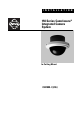
I N S T A L L A T I O N 150 Series Camclosure® Integrated Camera System In-Ceiling Mount C2410M-I (1/06)
Important Safety Instructions 1. Read these instructions. 2. Keep these instructions. 3. Heed all warnings. 4. Follow all instructions. 5. Do not block any ventilation openings. Install in accordance with the manufacturer’s instructions. 6. Do not install near any heat sources such as radiators, heat registers, stoves, or other apparatus (including amplifiers) that produce heat. 7. Only use attachments/accessories specified by the manufacturer. 8.
Regulatory Notices This device complies with Part 15 of the FCC Rules. Operation is subject to the following two conditions: (1) this device may not cause harmful interference, and (2) this device must accept any interference received, including interference that may cause undesired operation.
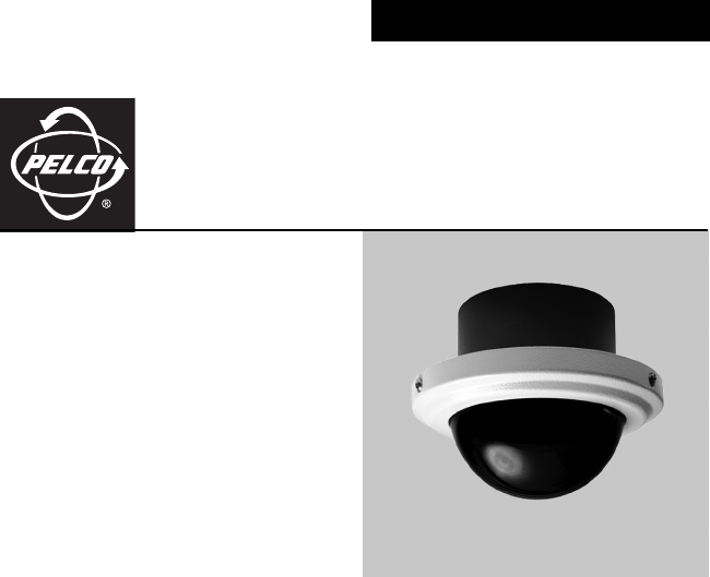
Description The 150 Series Camclosure® integrated camera system is an in-ceiling dome incorporating a camera and lens package into a small, discreet, high-security enclosure designed for areas subject to heavy vandalism. The system is perfect for a variety of indoor and outdoor applications and its versatile design allows for multiple mounting options.
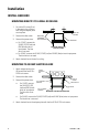
Installation INSTALL BACK BOX MOUNTING DIRECTLY TO A WALL OR CEILING 1. Cut a hole 3.5 inches (9 cm) in diameter in the ceiling or wall using the adapter plate as a template. 2. Connect the video cable. 3. Connect the power wires. WALL OR CEILING MOUNTING HARDWARE (NOT SUPPLIED) BACK BOX • For 12 VDC, connect the 24 VAC/12 VDC (red) and MOUNTING DIRECTLY TO GND (black) wires to WALL OR CEILING input power. The blue wire is not used.
MOUNTING TO CEILING TILE 1. Remove the ceiling tile. 2. Using the adapter plate as a template, cut a hole 3.5 inches (9 cm) in diameter in the ceiling tile for the back box. Punch four screw holes in the ceiling tile. 3. Attach the back box to the ceiling tile and adapter plate with the four 8-32 x 1.25-inch screws (see diagram). ADAPTER PLATE CEILING TILE 8-32 X 1.25 MOUNTING HARDWARE (SUPPLIED) BACK BOX MOUNTING TO CEILING TILE 4. Replace the ceiling tile. 5.
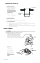
3. If the heater is installed, plug the heater connector from the camera into the mating connector inside the base. Plug the video connector from the camera into the mating connector inside the base. Turn on power to the camera and monitor. 4. If you have a varifocal lens, hold the assembly in your hand and point the lens toward what you want to view. Loosen the focal length and focus locking screws. Adjust according to scene detail. Retighten the screws.
INSTALL DOME AND TRIM RING Place the trim ring and dome over the back box. If the dome has a liner, position the viewing window over the lens of the camera. Tighten the tamper-resistant screws with the supplied 1/8-inch hollow screwdriver bit. Note that the screws are installed at an angle. Adjustments (Color Camera Only) If you have a color camera, it is set up at the factory and normally requires no adjustments. Sometimes, however, adjustments may be necessary. 1.
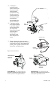
AUTO IRIS LEVEL ADJUSTMENT If you have a varifocal lens or fixed focal length lens with an auto iris, you can adjust the level setting to increase or decrease brightness. FIXED LENS VARIFOCAL LENS VERTICAL PHASE ADJUSTMENT AUTO IRIS LEVEL ADJUSTMENT FOCUS ADJUSTMENT FOR FIXED FOCAL LENGTH LENS WITH AUTO IRIS .
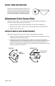
SWITCH SETTINGS FOR FIXED FOCAL LENGTH LENS WITH AUTO IRIS Refer to the switch drawing. The switch is located next to the lens. Automatic backlight compensation (factory setting) is used under varying lighting conditions (such as outdoors) or fixed lighting conditions where there are no bright spots that darken other picture details. Manual backlight compensation is used in fixed lighting conditions to optimize the picture detail when there are bright spots.
SWITCH SETTINGS FOR VARIFOCAL LENS AE Functions The high resolution camera with varifocal lens and auto iris is configured at the factory for automatic exposure.
Specifications GENERAL Operating Temperature -50° to 122°F (-46° to 50°C) De-ices to 25°F (-4°C) Pan/Tilt Adjustment Construction Manual; 360° pan; 180° tilt Aluminum with steel camera mounting bracket and polycarbonate dome White polyester powder coat trim ring with charcoal gray back box Refer to dimension drawing below Low temperature, indoor/outdoor, suitable for use in environmental air handling spaces 1.70 lb (0.
PRODUCT WARRANTY AND RETURN INFORMATION WARRANTY Pelco will repair or replace, without charge, any merchandise proved defective in material or workmanship for a period of one year after the date of shipment. Exceptions to this warranty are as noted below: • Five years on FT/FR8000 Series fiber optic products. • Three years on Genex® Series products (multiplexers, server, and keyboard).
REVISION HISTORY Manual # C2410M Date 11/99 Comments Original version. C2410M 1/00 C2410M-A 1/00 Revised installation instructions. Added FCC notices. Added varifocal lens. Changed format. C2410M-B 7/00 Added information on dome liner. C2410M-C 1/01 Added heater element caution. C2410M-D 7/01 Camera module redesigned, reference ECO 1-7054/7055/7056. C2410M-E 7/02 Added instructions for fixed lens with auto iris.
Worldwide Headquarters 3500 Pelco Way Clovis, California 93612 USA USA & Canada Tel: 800/289-9100 Fax: 800/289-9150 International Tel: 1-559/292-1981 Fax: 1-559/348-1120 www.pelco.