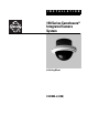
I N S T A L L A T I O N 150 Series Camclosure® Integrated Camera System In-Ceiling Mount C2410M-J (2/08)
Contents Important Safety Instructions. . . . . . . . . . . . . . . . . . . . . . . . . . . . . . . . . . . . . . . . . . . . . . . . . . . . . . . . . . . . . 3 Regulatory Notices . . . . . . . . . . . . . . . . . . . . . . . . . . . . . . . . . . . . . . . . . . . . . . . . . . . . . . . . . . . . . . . . . . . . . 4 Description . . . . . . . . . . . . . . . . . . . . . . . . . . . . . . . . . . . . . . . . . . . . . . . . . . . . . . . . . . . . . . . . . . . . . . . . . . . 5 Installation . . . . . . .
Important Safety Instructions 1. Read these instructions. 2. Keep these instructions. 3. Heed all warnings. 4. Follow all instructions. 5. Do not block any ventilation openings. Install in accordance with the manufacturer’s instructions. 6. Do not install near any heat sources such as radiators, heat registers, stoves, or other apparatus (including amplifiers) that produce heat. 7. Only use attachments/accessories specified by the manufacturer. 8.
Regulatory Notices This device complies with Part 15 of the FCC Rules. Operation is subject to the following two conditions: (1) this device may not cause harmful interference, and (2) this device must accept any interference received, including interference that may cause undesired operation. Radio and Television Interference This equipment has been tested and found to comply with the limits of a Class B digital device, pursuant to Part 15 of the FCC Rules.
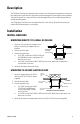
Description The 150 Series Camclosure® integrated camera system is an in-ceiling dome incorporating a camera and lens package into a small, discreet, high-security enclosure designed for areas subject to heavy vandalism. The system is perfect for a variety of indoor and outdoor applications and its versatile design allows for multiple mounting options. The ICS150 Series Camclosure can be installed directly to a wall, ceiling, 4S electrical box (using the optional ICS150 adapter plate), or a ceiling tile.
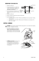
MOUNTING TO CEILING TILE ADAPTER PLATE 1. Remove the ceiling tile. 2. Using the adapter plate as a template, cut a hole 3.5 inches (9 cm) in diameter in the ceiling tile for the back box. Punch four screw holes in the ceiling tile. 3. Attach the back box to the ceiling tile and adapter plate with the four 8-32 x 1.25-inch screws. CEILING TILE 8-32 X 1.25 MOUNTING HARDWARE (SUPPLIED) BACK BOX MOUNTING TO CEILING TILE 4. Replace the ceiling tile. 5.
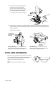
3. If the heater is installed, plug the heater connector from the camera into the mating connector inside the base. Plug the video connector from the camera into the mating connector inside the base. Turn on power to the camera and monitor. VIDEO CONNECTOR HEATER CONNECTOR 4. Always make sure the tab on the camera bracket is pointing out of the enclosure (away from the ceiling or wall). Gently squeeze the bracket, place it against the shoulder inside the back box, and then gently release.
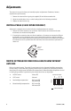
Adjustments The camera is set up at the factory and normally requires no adjustments. Sometimes, however, adjustments may be necessary. 1. Remove the dome and trim ring using the supplied 1/8-inch hollow screwdriver bit. 2. Adjust the vertical phase, focus, or switch settings (refer to the following procedures). 3. Replace the dome and trim ring. VERTICAL PHASE (24 VAC OPERATION ONLY) Adjustment is required if there is vertical roll when switching between two cameras. 1.
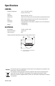
Specifications GENERAL Operating Temperature Pan/Tilt Adjustment Construction Finish Dimensions Environment Weight -50° to 122°F (-46° to 50°C) De-ices to 25°F (-4°C) Manual; 360° pan, 180° tilt Aluminum with steel camera mounting bracket and polycarbonate dome White polyester powder coat trim ring with charcoal gray back box Refer to dimension drawing below Low temperature, indoor/outdoor, suitable for use in environmental air handling spaces 1.70 lb (0.
PRODUCT WARRANTY AND RETURN INFORMATION WARRANTY Pelco will repair or replace, without charge, any merchandise proved defective in material or workmanship for a period of one year after the date of shipment. Exceptions to this warranty are as noted below: • • • • • • • • • • • • • • Five years on fiber optic products and TW3000 Series unshielded twisted pair (UTP) transmission products. Three years on Spectra® IV products. Three years on Genex® Series products (multiplexers, server, and keyboard).
REVISION HISTORY Manual # C2410M C2410M C2410M-A C2410M-B C2410M-C C2410M-D C2410M-E C2410M-F Date 11/99 1/00 1/00 7/00 1/01 7/01 7/02 5/03 C2410M-G 1/04 C2410M-H 10/05 C2410M-I C2410M-J 1/06 2/08 C2410M-J (2/08) Comments Original version. Revised installation instructions. Added FCC notices. Added varifocal lens. Changed format. Added information on dome liner. Added heater element caution. Camera module redesigned, reference ECO 1-7054/7055/7056. Added instructions for fixed lens with auto iris.
Worldwide Headquarters 3500 Pelco Way Clovis, California 93612 USA USA & Canada Tel: 800/289-9100 Fax: 800/289-9150 International Tel: 1-559/292-1981 Fax: 1-559/348-1120 www.pelco.