INSTALLATION/OPERATION C10DN Series Camera Day/Night, Ultra High Resolution C2944M-G (6/09)
Contents Important Safety Instructions . . . . . . . . . . . . . . . . . . . . . . . . . . . . . . . . . . . . . . . . . . . . . . . . . . . . . . . . . . . . . . . . . . . . . . . . . . . . . . . . . . . . . . . . . . . . 5 Regulatory Notices . . . . . . . . . . . . . . . . . . . . . . . . . . . . . . . . . . . . . . . . . . . . . . . . . . . . . . . . . . . . . . . . . . . . . . . . . . . . . . . . . . . . . . . . . . . . . . . . . . . . 6 Equipment Handling Precautions . . . . . . . . . . . . . . . . . .
List of Illustrations 1 2 3 4 5 6 7 8 C10DN Series Camera . . . . . . . . . . . . . . . . . . . . . . . . . . . . . . . . . . . . . . . . . . . . . . . . . . . . . . . . . . . . . . . . . . . . . . . . . . . . . . . . . . . . . . . . . . . . . 8 DC Drive Auto Iris Lens Connector . . . . . . . . . . . . . . . . . . . . . . . . . . . . . . . . . . . . . . . . . . . . . . . . . . . . . . . . . . . . . . . . . . . . . . . . . . . . . . . . . . . . 9 Mounting Lens to Camera . . . . . . . . . . . . . . . . . . .
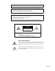
WARNING: TO PREVENT RISK OF FIRE OR SHOCK, DO NOT EXPOSE THIS CAMERA TO RAIN OR MOISTURE. PRECAUTION: DO NOT REMOVE ANY COVER WHILE THE CAMERA IS OPERATING. PAL: USE ONLY RECOMMENDED POWER SUPPLY, 220 TO 240 VAC, 50 Hz. CAUTION: LENS MOUNT OF THE CAMERA IS “CS” MOUNT. CAMERA LENS MOUNT IS SHALLOW, SOME CAMERA LENSES MAY BOTTOM OUT AND DAMAGE THE CCD IMAGER. DO NOT TOUCH THE CCD GLASS SURFACE. THE CAMERA MUST BE INSTALLED NEAR A SOCKET OUTLET, WHICH COULD BE EASILY ACCESSIBLE.
Important Safety Instructions 1. Read Instructions. All the safety and operating instructions should be read before the camera is operated. 2. Retain Instructions. The safety and operating instructions should be retained for future reference. 3. Heed Warnings. All warnings on the camera and in the operating instructions should be adhered to. 4. Follow Instructions. All operating and use instructions should be followed. 5. Cleaning: Unplug the power unit from the wall outlet before cleaning.
Regulatory Notices This device complies with Part 15 of the FCC Rules. Operation is subject to the following two conditions: (1) this device may not cause harmful interference, and (2) this device must accept any interference received, including interference that may cause undesired operation. RADIO AND TELEVISION INTERFERENCE This equipment has been tested and found to comply with the limits of a Class B digital device, pursuant to Part 15 of the FCC Rules.
Description The C10DN Series camera is Pelco’s smallest day/night camera. Its day/night technology provides outstanding performance over a wide range of lighting conditions. The camera also uses a removable infrared (IR) cut filter to switch between color and black-white (B-W) modes as environmental lighting conditions change. On-screen programmable menus can be accessed using the side panel controls. Use these menus to customize camera settings for the specific application.
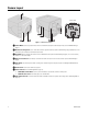
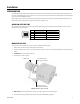
Camera Layout C10DN-7X BACK Figure 1. C10DN Series Camera ì Camera Mount: Use the top or bottom mount hole. The maximum thread depth is 0.25 inches (6.4 mm); refer to Camera Mounting on page 10. î Back Focus Locking Screw: Use a 1.5-mm Allen wrench to adjust the back focus (refer to Lens Focusing on page 25). Back focus is set at the factory for a standard CS-mount back focus distance. ï Lens Mount: Mount a standard CS-mount lens to the C10DN Series camera (refer to Lens Mounting on page 9).
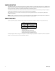
Installation LENS MOUNTING The C10DN Series camera supports both manual and auto iris lenses, either fixed focal length or varifocal. It also supports both DC and video drive lenses. It automatically senses an auto iris lens as soon as you plug in the connector. The camera has a standard CS mount that can accept a C-mount lens with a PCMA40 lens adapter.
CAMERA MOUNTING The C10DN Series camera can be mounted from either the top or bottom, depending on the type of camera mount used in your installation. Use a standard 1/4-20 screw. The maximum thread depth (top) is 0.188 inches (4.7 mm). To extend the thread depth (top) to 0.25 inches (6.4 mm), use the camera mount spacer (supplied). The maximum thread depth (bottom) is 0.25 inches (6.4 mm).
CONNECTING POWER The C10DN-6 and C10DN-6X are designed to operate from either a 12 VDC or a 24 VAC power source. The camera automatically senses power type. Use only a Class 2 isolated power source that can supply 12 VDC ±15% or 24 VAC ±15%, 50/60 Hz. Maximum power consumption is about 3.5 W. WARNINGS: • Do not connect high voltage power to the camera because you may damage the camera. • Do not short circuit the power leads when connecting the power supply to the camera.
CONNECTING AC POWER The C10DN Series camera requires a power supply of 24 VAC ±15% 20.4–27.6 VAC, 50/60Hz. Make sure the power supply has a minimum rating of 270 mA.
CONNECTING DC POWER The C10DN Series camera requires a power supply of 12 VDC ±15% 10.2–13.8 VDC. Make sure the power supply has a minimum rating of 390 mA. WARNINGS: • For safety, include a 1.0 A slow blow fuse when connecting DC power, as shown in Figure 5. • The DC power supply must be UL and CE certified. • Make sure you wire the power polarity correctly. To connect DC power refer to Figure 5, and then complete the following steps: 1. Strip at least 0.
CONNECTING DAY/NIGHT FILTER CONTROL In some installations, high infrared (IR) illumination or other light sources may interfere with the camera’s automatic day/night mode operation. Use an external day/night filter switch, such as a photosensor, to keep the camera from constantly switching filters. The control signal input responds as shown in Table C. Table C. Day/Night Control Signal Signal Open or High Short or Low Voltage 3.0 V to 3.3 V -0.3 V to 0.
Accessing the Setup Menus Use the five-position button controller on the side panel of the camera to access and navigate the on-screen display (OSD) menus (refer to Figure 7 and Table D). LEFT UP SELECT RIGHT DOWN Figure 7. Side Panel Button Options Table D. Accessing the OSD Menu Menu Options Display the MAIN MENU on the screen. Move the cursor up or down in a menu; or toggle through menu selections. Move the cursor right or left in a menu. Select menu or make a menu selection.
Setup Menus The C10DN Series camera uses setup menus instead of hardware switches for configuring the camera. As a result, you have more options for customizing the camera for its specific application. NOTE: After you customize any aspect of the C10DN Series camera, be sure to save your custom settings. (Refer to Profiles on page 18 for information about saving custom settings.) PROFILES STANDARD GAMING CUSTOM BACK MAIN MENU PROFILES EXPOSURE SET. FUNCTION SET.
MAIN MENU The following sections describe each menu and the settings associated with that menu. The sample screens in each section show the default settings. To display the MAIN MENU, complete the following steps: 1. Press and hold the center button on the side of the camera (refer to Accessing the Setup Menus on page 15). MAIN MENU PROFILES EXPOSURE SET. FUNCTION SET. SAVE AS CUSTOM PIXEL CORRECTION SYSTEM INFORMATION -> -> -> -> -> -> EXIT 2. Use the Pelco controller to navigate through the menus.
PROFILES Use this option to select a profile or save custom settings. Use profiles for faster installation or to adjust camera settings quickly for changing light conditions. The default setting is DAY&NIGHT. The C10DN Series camera offers three predefined profiles and one custom, or user-definable, profile. You cannot modify predefined profiles. PROFILES STANDARD GAMING CUSTOM BACK EXIT ACTIVE Select one of the following application profiles: STANDARD: Select this profile for most scenes.
EXPOSURE SETTINGS EXPOSURE SET. Select this option to configure the exposure settings for the C10DN Series camera. AUTO EXPOSURE The automatic exposure feature automatically adjusts the electronic shutter and mechanical iris to set the correct exposure. Default settings depend on the selected profile (refer to Table E on page 18.
DC IRIS LEVEL Select this option to adjust the electronic properties of the DC drive auto iris lens to the auto iris electronic properties of the camera. Perform this procedure before using the camera or each time you change the lens. To perform this procedure, complete the following steps: 1. Focus the camera (refer to Lens Focusing on page 25). 2. Aim the camera at a bright, flickerless scene. 3. Select DC IRIS LEVEL from the MAIN MENU. 4. Adjust the DC IRIS LEVEL value (for the best image).
DETECT TIME The camera regularly checks the brightness level. When the brightness level crosses the switch threshold and lasts longer than the D&N DETECTION setting, the camera switches the filter. For example, the headlights of a passing car affect the brightness level in the camera, but not long enough for the filter to switch. The constant light from a cloudy day also affects the brightness level in the camera, long enough for the filter to switch. Select one of the following options: 5 SEC, 30 SEC.
WHITE BALANCE The C10DN Series camera offers three white balance options. White balance settings define how the camera processes video images to render true colors in a scene. White balance is especially effective in scenes with changing color temperatures. Use it also in installations with incandescent, fluorescent, or outdoor lighting. Select one of the following white balance modes: AUTO: In this mode, the camera automatically adjusts the white balance based on the colors in the camera scene.
MASKING MASKING Masking lets you block certain areas of a camera scene. A maximum of eight masks can be defined. NOTE: If you add a ninth mask, the camera erases the first mask. You cannot configure more than eight masks. MASK MASK COLOR MASK EDIT MASK ERASE BACK MASK: -> OFF -> -2 -> 0 EXIT Use this option to enable or disable masking; the default setting is OFF. MASK COLOR: Use this option to select the color of the mask. Available settings are black, white, gray, red, green, blue, and yellow.
SAVE AS CUSTOM Select this option to create and save a custom profile. Whenever you open and make changes to the EXPOSURE SET and FUNCTION SET menus, the camera stores the settings. These setting can be saved as a custom profile. SAVE AS CUSTOM CURRENT SETTING ARE SAVED OK CANCEL To save defined exposure and function settings as a CUSTOM profile, complete the following steps: 1. Move the cursor to the SAVE AS CUSTOM menu. 2. Press the menu selection button, the SAVE AS CUSTOM menu is displayed. 3.
Lens Focusing After mounting the lens, you must focus your C10DN Series camera. You will adjust both the back focus (on the camera) and the fine focus (on the lens). NOTE: The back focus has already been adjusted using a standard CS-mount lens. However, you might need to adjust it again to match the mounted lens. 1. Auto iris only: Cover the auto iris lens with a suitable neutral density (ND) filter; this opens the iris fully. For best results, use an ND3 filter. 2.
6. Varifocal lens only: a. b. Set the varifocal to wide (W) and the lens focal length to far (∞). Adjust the back focus: (1) Use a 1.5-mm Allen wrench to loosen the back focus locking screw. (2) Turn the lens until the image is focused. (3) Tighten the back focus locking screw clockwise. WARNING: Do not overtighten the back focus locking screw because you may damage the camera. (Back focus is a coarse adjustment. You will make the fine focus adjustment in steps c and d.) c.
Camera Synchronization Camera synchronization may affect installations that use two or more AC power supplies for multiple cameras. Due to different power phases, a brief vertical roll may appear on the monitor when switching between cameras. To eliminate this vertical roll, adjust the phase control to synchronize the cameras to one another.
Manual White Balance Calibration In some installations, use manual white balance to render the most accurate image color possible. Mixed color applications may affect the amount of color adjustment. For example, a small white object on a large blue surface may have a reddish tint. The HOLD white balance setting uses a calibration image to identify the correct white level. The camera then uses this white level when adjusting overall image color.
Specifications GENERAL Day/Night Operation Day Night Infrared (IR) cut filter BK-7 glass, same optical displacement as day Imaging Device 1/3-inch interline transfer CCD Picture Elements NTSC PAL 768 (H) x 494 (V) (approx. 380 k) 752 (H) x 582 (V) (approx. 440 k) Sensing Area 3/16 x 1/8-inch (4.7 x 3.
ENVIRONMENTAL Operating Temperature 14° to 122°F (-10° to 50°C) Storage Temperature -4° to 140°F (-20° to 60°C) Operating Humidity 20% to 80% (noncondensing) Storage Humidity 20% to 90% (noncondensing) PHYSICAL Dimensions C10DN-6/C10DN-6X C10DN-7X 2.95" L x 2.17" W x 1.97" H (7.5 x 5.5 x 5.0 cm) 5.50" L x 2.17" W x 1.97" H (13.97 x 5.5 x 5.0 cm) Weight (without lens) C10DN-6/C10DN-6X C10DN-7X 0.44 lb (0.20 kg) 0.88 lb (0.40 kg) Shipping Weight C10DN-6/C10DN-6X C10DN-7X 1 lb (0.45 kg) 2 lb (0.
PRODUCT WARRANTY AND RETURN INFORMATION WARRANTY Pelco will repair or replace, without charge, any merchandise proved defective in material or workmanship for a period of one year after the date of shipment.
www.pelco.com Pelco, Inc.