I N S T A L L A T I O N ® ExSite™ Series Explosionproof Camera Module C1303M-B (5/05)
Important Safety Instructions 1. Read these instructions. 2. Keep these instructions. 3. Heed all warnings. 4. Follow all instructions. 5. Do not block any ventilation openings. Install in accordance with the manufacturer’s instructions. 6. To reduce the risk of ignition of hazardous atmospheres, disconnect the equipment from the supply circuit before opening. Keep assembly tightly closed when in operation. 7. The maximum ambient temperature range is -76°F to 140°F (-60°C to 60°C). 8.
Getting Started Thank you for purchasing Pelco’s ExSite™ Series explosionproof integrated positioning system. This manual includes instructions for installing the camera module for the ExSite Series system. For complete system installation instructions, refer to the installation manual placed in the pan and tilt box. WARNING: Do not connect the power module to a supply circuit unless all ExSite system components (pan and tilt, camera module, and power module) are installed.
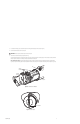
Installation To install the camera module do the following: 1. Refer to Figure 1. Loosen the set screw at the back of the enclosure with the provided 1.5 mm Allen wrench. SET SCREW Figure 1. Loosen Setscrew 2. Use the supplied spanner wrench to loosen the back of the camera enclosure (refer to Figure 2). Once the back is loose, use your hands to continue to loosen it until it can be removed. WARNING: To avoid thread damage, carefully remove the back of the enclosure.
3. Slide the camera module into the enclosure. Refer to Figure 3 to position the camera module properly in the enclosure. Carefully mate the camera’s power connector to the mating connector located inside the enclosure. Only models with wipers: The tab located inside the enclosure must be pointing down before installing the camera module (refer to Figure 3). To position the tab, place the wiper located at the front of the enclosure in the center of the viewing window (refer to Figure 4).
4. Refer to Figure 5 and do the following to install the arm of the wiper: a. Place the supplied green bushing on the stud located behind the handle of the camera module. The bushing should be in the same orientation as shown in Figure 5. b. Install the wiper arm. Place the ridge of the arm in the notch of the enclosure tab and the slot of the arm over the green bushing. 5. Secure the arm of the wiper and the camera module with the supplied 8-32 Phillips flat head screw (refer to Figure 5).
Maintenance CAMERA MODULE REPLACEMENT The ExSite camera module can be replaced only with a camera module with the same model number. If a different camera model is installed in an existing system, the system will not function and a message to contact the Pelco factory will appear on the screen. DANGER: To reduce the risk of ignition of hazardous atmospheres, disconnect the equipment from the power supply before opening. Keep assembly tightly closed when operating.
3. For models with wipers, also remove the wiper arm and the green bushing from the unit (see Figure 7). 4. Slide the camera module out of the enclosure. WARNING: Never force the camera module into the enclosure. 5. Install the new camera module by doing the following: Slide the camera module into the enclosure. Refer to Figure 8 to position the camera module properly in the enclosure. Carefully mate the camera’s power connector to the mating connector located inside the enclosure.
6. Refer to Figure 7 and do the following to reinstall the arm of the wiper: a. Reinstall the green bushing on the stud located behind the handle of the camera module. b. Reinstall the wiper arm. Place the ridge of the arm in the notch of enclosure tab and the slot of the arm over the green bushing. 7. Secure the camera module and the wiper arm with the 8-32 Phillips flat head screw (refer to Figure 7). WARNINGS: • To avoid thread damage, carefully install the back cap to the enclosure.
Specifications Camera Signal Format Scanning System Image Sensor Effective pixels NTSC PAL Horizontal Resolution NTSC PAL Lens Zoom Zoom Speed Horizontal Angle of view Focus Maximum Sensitivity at 35 IRE NTSC PAL Sync System White Balance Shutter Speed NTSC PAL Iris Control Gain Control Video Output Video Signal to Noise Day/Night (23X) Color NTSC, PAL 2:1 interlace 1/4-inch CCD LowLight™ (22X) Color NTSC, PAL 2:1 Interlace 1/4-inch EXview HAD™ CCD 724 (H) x 494 (V) 724 (H) x 582 (V) 768 (H) x 494 (V)
Worldwide Headquarters 3500 Pelco Way Clovis, California 93612 USA USA & Canada Tel: 800/289-9100 Fax: 800/289-9150 International Tel: 1-559/292-1981 Fax: 1-559/348-1120 www.pelco.