® Installation/Operation CC3701H-2 and CC3701H-2X DSP Color Camera with EDR C1937M-C (4/03) Pelco World Headquarters • 3500 Pelco Way, Clovis, CA 93612-5699 USA • www.pelco.
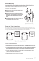
IMPORTANT SAFEGUARDS AND WARNINGS Prior to installation and use of this product, the following WARNINGS should be observed. 1. Read these instructions. 2. Keep these instructions. 3. Heed all warnings. 4. Follow all instructions. 5. Do not use this apparatus near water. 6. Clean only with dry cloth. 7. Do not block any ventilation openings. Install in accordance with the manufacturer’s instructions. 8.
REGULATORY NOTICES This equipment has been tested and found to comply with the limits of a Class B digital device, pursuant to part 15 of the FCC rules. These limits are designed to provide reasonable protection against harmful interference in a residential installation. This equipment generates, uses, and can radiate radio frequency energy and, if not installed and used in accordance with the instructions, may cause harmful interference to radio communications.
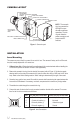
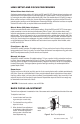
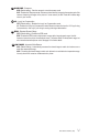
CAMERA LAYOUT BACK FOCUS ADJUSTMENT MOUNT ADAPTER LOCKING SCREW PHASE ADJUSTMENT LENS LEVEL ADJUSTMENT POWER CONNECTOR COSMETIC TRIM RING BACK FOCUS ADJUSTMENT RING BNC VIDEO CONNECTOR LED LENS CONNECTOR DIP SWITCHES (COVER REMOVED) 20156 NOTE: The cosmetic trim ring conceals the LED light for more discreet surveillance operations. The trim ring also hides the power connectors and protects the DIP switches. Figure 1.
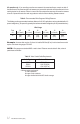
Camera Mounting Use a standard 1/4-20 screw (provided) with a maximum thread length of 3/8-inch (10 mm) for top or bottom camera mounting. The mount adapter may be fitted to the top or bottom of the camera. The camera is shipped with the mount adapter located on the top of the camera. 1 To change the mount adapter position: 2 1 Remove the four screws from the mount adapter located on the top of the camera. 2 Remove the trim cover from the bottom of the camera by prying it loose.
AC operation only - If you are wiring more than one camera to the same transformer, connect one side of the transformer to the same terminal on all cameras, and connect the other side of the transformer to the remaining terminal on all cameras. Failure to connect all of the cameras the same way will cause the cameras to be out of phase with each other and may produce a vertical roll when switching between cameras. Table A.
LENS SETUP AND FOCUS PROCEDURES Video Drive Auto Iris Lens Set the lens mode selector switch to AIV. Switch the ESC and AGC OFF. Refer to the lens instructions and adjust the lens for the optimum picture (video output level of 1V peak-to-peak). To focus, fully open the iris by covering the lens with a suitable neutral density (ND*) filter. If the viewed scene is 6.5 feet (2 m) away or farther, set the lens focus to infinity (far).
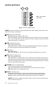
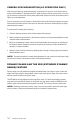
SWITCH SETTINGS - + PHASE H LEVEL ON OFF OFF L BLC AGC 1 3 OFF OPT ESC AIV AID 5 INT LL OFF NOR OFF OFF AW1 2 4 Note: White indicates switch setting. 6 SHP LC 7 EDR 9 8 AW2 10 20157 Figure 6. DIP Switch Default Settings NOTE: Under most conditions, no setting of switches will be required. Please read the details of each switch before making any adjustments. 1 BLC - Back Light Compensation OFF (Default setting) - Disables the BLC mode. BLC - Enables the BLC mode.
7 NOR/SHP - Sharpness NOR (Default setting) - Sets the camera to normal sharpness mode. SHP - Enables the Sharpness mode. Enhances picture detail by increasing the aperture gain of the camera, sharpening the edges in the picture. In some scenes, the SHP mode will increase edge noise on your monitor. 8 LC - Long Line Compensation OFF (Default setting) - Disables the Long Line Compensation mode. LC - Enables the Long Line Compensation mode. Boosts the video drive level to 1.25 Vp-p for long line transmission.
CAMERA SYNCHRONIZATION (AC OPERATION ONLY) When using more than one camera power supply, a brief vertical roll may occur on the monitor when a camera view is switched. To eliminate vertical roll, adjust the phase control by synchronizing, or line-locking, the cameras to one another. Use the phase potentiometer located on the side of the camera (refer to Figure 1) to make adjustments.
SPECIFICATIONS GENERAL CCD Sensor: Picture Elements CC3701H-2: CC3701H-2X: Sensing Area: Synchronize System: Horizontal Resolution CC3701H-2: CC3701H-2X: Iris Control: Minimum Illumination: ESC: Signal-to-Noise Ratio: Gain Control: Vertical Phase: Backlight Compensation: Scanning System CC3701H-2: CC3701H-2X: Signal Processing: Auto Iris Lens Type: Video Output: ELECTRICAL Power Requirements 24 VAC: 12 VDC: Power Consumption 1/3-inch interline transfer 768 (H) x 494 (V) 752 (H) x 582 (V) 6 mm diagonally I
WARRANTY AND RETURN INFORMATION WARRANTY Pelco will repair or replace, without charge, any merchandise proved defective in material or workmanship for a period of one year after the date of shipment. Exceptions to this warranty are as noted below: • • • • • • • • • • Five years on Pelco manufactured cameras (CC3500/CC3600/CC3700 and MC3500/MC3600 Series); two years on all other cameras. Three years on Genex® Series (multiplexers, server, and keyboard) and 090 Series Camclosure® Camera System.