INSTALLATION/OPERATION Public View Monitor C2943M-B (1/09)
C2943M-B (1/09)
Contents Important Safety Instructions . . . . . . . . . . . . . . . . . . . . . . . . . . . . . . . . . . . . . . . . . . . . . . . . . . . . . . . . . . . . . . . . . . . . . . . . . . . . . . . . . . . . . . . . . . . . 4 Regulatory Notices . . . . . . . . . . . . . . . . . . . . . . . . . . . . . . . . . . . . . . . . . . . . . . . . . . . . . . . . . . . . . . . . . . . . . . . . . . . . . . . . . . . . . . . . . . . . . . . . . . . . 5 Description. . . . . . . . . . . . . . . . . . . . . . . . . . . .
Important Safety Instructions 1. Read these instructions. 2. Keep these instructions. 3. Heed all warnings. 4. Follow all instructions. 5. Do not use this apparatus near water. 6. Clean only with dry cloth. 7. Do not block any ventilation openings. Install in accordance with the manufacturer’s instructions. 8. Do not install near any heat sources such as radiators, heat registers, stoves, or other apparatus (including amplifiers) that produce heat. 9.
Regulatory Notices This device complies with Part 15 of the FCC Rules. Operation is subject to the following two conditions: (1) this device may not cause harmful interference, and (2) this device must accept any interference received, including interference that may cause undesired operation. RADIO AND TELEVISION INTERFERENCE This equipment has been tested and found to comply with the limits of a Class A digital device, pursuant to Part 15 of the FCC Rules.
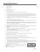
Description Public view monitors (PVM) are units that contain a built-in camera that is pointed in the direction the monitor faces. This allows customers to see themselves on the monitor. This feature makes the PVM ideal for commercial establishments because it creates interest, while discouraging theft. The PVM also includes connections for additional camera inputs, DVD players, and inputs for media cards.
Installation MOUNTING The PVM accommodates mounts that adhere to the VESA® 100 x 100 standard. For mounting from a ceiling, Pelco recommends using the PMCL-CM mount. This mount can be swiveled 360 degrees, and lets you tilt the monitor 35 degrees for the best viewing angle. This mount must be used with a pole to hang the monitor from a ceiling. The PMCL-CM can support a maximum load of 90 lb (40.8 kg).
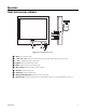
REAR PANEL CONNECTORS COVER ACCESS DOOR THUMBSCREW OUTPUT 24V AC~ INPUT USB CF SD Figure 2. Rear Panel Connectors ì 24 V AC~: The 24 volt AC power. NOTE: The center post is not to be used. î ï ñ ó Camera Out: The internal camera’s video output signal. Video 2 (loop through): The input connections from a camera or a DVD player. Video loops through the BNC video output. Video 1 (loop through): The input connections from a camera or a DVD player. Video loops through the BNC video output.
Operation FRONT AND SIDE PANEL CONTROLS VOL + VOL - SOURCE MENU Figure 3. Front and Side Panel Controls ì î ï ñ ó r s t u ~í C2943M-B (1/09) (Power): Turns on/off the monitor. !/VOL + and "/VOL-: Increases or decreases the volume. Also selects or adjusts items on the on-screen menu. # and $: Navigates through the on-screen menu. SOURCE: Selects and confirms the input source. MENU: Displays the main on-screen menu (monitor). (Built-In Camera): Displays the camera’s view on the monitor.
INSTALLING REMOTE CONTROL BATTERIES Figure 4. Battery Installation 1. Open and remove the back cover of the remote control. 2. Install two AAA size batteries (supplied). Match the plus (+) and minus (-) symbols on the batteries to the symbols on the battery compartment. 3. Close the battery cover. Make sure the lock snaps closed. WARNINGS: 10 • Dispose of batteries in a designated disposal area. Do not throw batteries into a fire. • Do not mix battery types.
REMOTE CONTROL FUNCTIONS MUTE ì î POWER: Turns on/off power to the monitor. ï VIDEO1/VIDEO2/MEDIA/CAMERA: Displays all the available input sources. Press the appropriate button to select the desired input source. ñ ó r COLOR TEMP: Adjusts the color temperature of the screen. POWER VIDEO1 VIDEO 2 MEDIA CAMERA PIP ON/OFF P. SIZE P. S WAP P. INPUT P. LOCATION CYCLE MENU/EXIT COLOR TEMP MUTE: Temporarily silences the sound. To return the sound, press MUTE again, or VOL + or VOL -.
OSD FUNCTION INPUT SOURCE DISPLAY VIDEO 1 VIDEO1 VIDEO2 CAMERA MEDIA Figure 6. Input Source Display Screen The input source is displayed in the upper-right corner, where it can be changed. It can be changed using the Source button on the monitor or using the buttons on the remote control (when the OSD Mode Label is set to ON). The default setting is OFF. To use the menus: 1. Press the MENU button to access the Main menu. 2. Use the up and down arrow buttons (# and $) to highlight a selection. 3.
MENU DISPLAY Brightness Menu 0 MAIN MENU PICTURE SCREEN SETUP PVM SETUP CYCLE SETUP CAMERA MAINTENANCE Default values are in bold Brightness Contrast Sharpness Color Tint Color Temp 50 Contrast Menu 100 0 50 Tint Menu 0 50 Color Menu 100 0 50 Scan Mode/PIP Scan Mode Menu Scan Mode PIP Mode PIP Input PIP Swap UNDER FULL OVER 4:3 PIR Mode PIR Sensitivity PIR Input PIR Dwell Green USER Blue 100 0 100 PIP Location Menu R/B L/B L/T R/T Sound Mute Menu Key Lock Menu ON OFF IQE ON OFF Lan
MENU FIELD DEFINITIONS PICTURE Brightness: Adjusts the white level of the video screen image (0 to 100). Contrast: Adjusts the black level of the video screen image (0 to 100). Sharpness: Adjusts the picture softer or sharper (0 to 15). Color: Adjusts the color saturation of the video signal (0 to 100). Tint: Adjusts the range of color: green to red (0 to 100). This function is only available in NTSC mode; it is not available in PAL/SECAM. Color Temp: Selects the temperature: Normal, Cool, or USER.
PVM SETUP Auto Power ON: Select the video input to be activated when power is restored after an electrical failure. Select OFF, VIDEO 1, VIDEO 2, CAMERA, or MEDIA. Light Sensor Mode: Automatically turns on or off the monitor based on the light intensity. L. Sensor Sensitivity: Sets the light intensity at which the monitor is turned off and on (1 to 100). The 100 setting is the more sensitive. Light Sensor Delay: Sets the time that the Auto Day/Night feature pauses before being activated (5 to 30 seconds).
MEDIA CONTROL Media Type Selection Screen SELECT MEDIA SELECT MEDIA TYPE Figure 9. Media Type Selection Screen The four choices available on the Media Type Selection screen are PHOTO (slides), MUSIC, MOVIE, and FILES. Photo Slide Show Select the photo slide show: 1. Press the MEDIA MENU button on the remote control to access the media menu. 2. Use the left and right arrow buttons ("and !) on the media portion of the remote control (refer to Figure 10) to highlight the PHOTO option, and then press ENTER.
Figure 11. Slide Show Screen 3. Select the desired picture using the left and right arrow buttons ("and !). Press PLAY (or ENTER) to play the slide show. If a picture is deselected, it will have a red highlight. To include a picture, it must have a green highlight. (Pressing ENTER while in the MUSIC option will not play the slide show.) 4. To change a setting value of the slide show option, press the MEDIA MENU button while in the slide show screen (refer to Figure 10 on page 16).
Slide Show Option Field Definitions TIME: Sets the length of time a selected picture displays on the screen in slide show mode: 1, 3, 5, or 10 seconds. The default setting is 5 seconds. EFFECT: Sets the display effect while changing to the next picture in slide show mode. • Random: Mixes the display effects below. The default setting is Random. • Full: Changes the displayed picture to the next picture in full-screen mode. • T/B (top>bottom): Fades in/out the next picture from top to bottom.
Movie Mode Select a movie: 1. Press the MEDIA MENU button on the remote control to access the media options. 2. Use the left and right arrow buttons ("and !) on the media portion of the remote control (refer to Figure 10 on page 16) to highlight the MOVIE option, and then press ENTER. 3. The program lists all available movie files on the screen. You can select the file you want to play. All compatible files listed will be played.
REPLACING THE CAMERA NOTE: You must wear lead-free gloves and use electrostatic discharge (ESD) equipment when handling cameras. CAMERA REMOVAL 1. Place the monitor face down, being careful not to scratch or touch the screen. 2. Use the thumb screw on the bottom of the monitor to open the access door. Refer to Figure 13. Figure 13. Access Door 3. Unscrew the three metric screws (14 mm) that secure the camera. Remove the screws and spacers. 4.
SW1-1 Reserved SW1-1 is controlled through the on-screen menu. Refer to System Menu in Figure 8 on page 13, and SYSTEM under the heading CAMERA on page 15 for more information. SW1-2 Reserved When multiple cameras are connected to the same switching device, vertical roll can occur on the monitor. AC line lock eliminates vertical roll by locking the frame rate to the power supply frequency. Each camera output is synchronized to the power supply frequency.
CAMERA INSTALLATION AND CAMERA ADJUSTMENT 1. Plug the two camera connection leads from inside the monitor into the connectors on the camera. These connectors are keyed and only fit in the correct receptacles, so confusing the connectors is not possible. 2. Attach the camera using three spacers and three screws (14 mm). Do not overtighten the screws or the spacers will collapse. The focus knobs need to be positioned as shown in Figure 15. 3. Tuck the camera leads neatly into the monitor. 4.
Specifications MODELS PMP20B 20-inch (510 mm) LCD black monitor with WDR camera PMP20W 20-inch (510 mm) LCD white monitor with WDR camera PMP26B 26-inch (660 mm) LCD black monitor with WDR camera PMP26W 26-inch (660 mm) LCD white monitor with WDR camera GENERAL Native Resolution PMP20B, PMP20W PMP26B, PMP26W 640 x 480 VGA 1366 x 768 WXGA Horizontal Resolution PMP20B, PMP20W PMP26B, PMP26W 480 TVL 600 TVL Panel Aspect Ratio PMP20B, PMP20W PMP26B, PMP26W 4:3 16:9 Viewing Area PMP20B, PMP20W PMP2
ELECTRICAL Input Voltage 24 VAC (50/60 Hz) Power Consumption PMP20B, PMP20W PMP26B, PMP26W 96 W (4.0 A) 160 W (6.7 A) Input Interfaces Video: 2 BNC Media card (refer to General on page 23) Output interfaces 1 BNC Camera Horizontal Frequency 15.75/16.
LENS SPECIFICATIONS Focal Length 3.0 mm to 9.5 mm Format Size 1/3-inch F-Number f/1.0~1.8 Operation Iris Focus Zoom Auto Manual Manual Angle of View* Horizontal Diagonal Vertical 100.4° to 31.6° 131.6° to 39.6° 72.8° to 23.8° *Focal length specifications presume a 10% horizontal and 4% vertical monitor overscan.
C2943M-B (1/09)
PRODUCT WARRANTY AND RETURN INFORMATION WARRANTY Pelco will repair or replace, without charge, any merchandise proved defective in material or workmanship for a period of one year after the date of shipment.
www.pelco.com Pelco, Inc.