
User's Manual


14 C2953M-B (10/09)
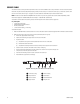
ALARM, RELAY, AND 24 VAC CONNECTOR
Single Camera Wiring
If PoE is not available:
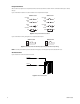
1. Connect the alarm, relay, and 24 VAC wires to the supplied mating connector (refer to Figure 8).
NOTE: Only use the 24 VAC wires if PoE is not available.
2. When finished, attach the mating connector to the green connector on the back of the camera.
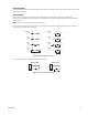
Multiple Camera Wiring
If you are operating the camera using 24 VAC and you are wiring more than one camera to the same transformer:
1. Connect one side of the transformer to pin 1 of the 2-position terminal block on all modules.
2. Connect the other side of the transformer to pin 2 of the terminal block on all modules.
NOTE: Failure to connect all modules identically might introduce video noise for some installations.
Figure 8. Alarm, Relay, and 24 VAC Connector
Connecting a Relay Device
The camera has an output for activating an external device. It supports both momentary and continuous relay operation.
You can operate the relay interactively during an active connection, or it can operate automatically to coincide with certain events. Typical
applications include turning on lights or other electrical devices or activating a door, gate, or lock.
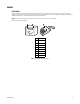
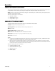
Figure 9 shows how to wire the relay with its power source to the camera.
Figure 9. Relay Wiring
WARNING: Do not exceed the maximum rating of 12 VDC, 0.15 A.
24V~
RELAY
R1
ALARM
A1
12 VDC, 150 mA MAX
24V~
R1
A1