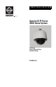
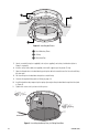
I N S T A L L A T I O N Spectra IV IP Series SD4E Dome System In-Ceiling Heavy-Duty In-Ceiling Pendant (shown) C3468M (4/10)
Contents Important Notices. . . . . . . . . . . . . . . . . . . . . . . . . . . . . . . . . . . . . . . . . . . . . . . . . . . . . . . . . . . . . . . . . . . . . . Legal Notice . . . . . . . . . . . . . . . . . . . . . . . . . . . . . . . . . . . . . . . . . . . . . . . . . . . . . . . . . . . . . . . . . . . . . Regulatory Notices. . . . . . . . . . . . . . . . . . . . . . . . . . . . . . . . . . . . . . . . . . . . . . . . . . . . . . . . . . . . . . . . Open Source Software Notice . . . . . . . . . . .
List of Illustrations 1 2 3 4 5 6 7 8 9 10 11 12 13 14 15 16 17 18 19 20 4 Preparing the Ceiling . . . . . . . . . . . . . . . . . . . . . . . . . . . . . . . . . . . . . . . . . . . . . . . . . . . . . . . . . . . . . . 8 Attaching the Conduit Fitting, Lock Nut, and Safety Chain Bracket . . . . . . . . . . . . . . . . . . . . . . . . . . 8 Marking the Screw Hole Pattern . . . . . . . . . . . . . . . . . . . . . . . . . . . . . . . . . . . . . . . . . . . . . . . . . . . . . 9 Installing the Plates . . .
List of Tables A B C D E F Video Coaxial Cable Requirements . . . . . . . . . . . . . . . . . . . . . . . . . . . . . . . . . . . . . . . . . . . . . . . . . . 24 VAC/24 VDC Wiring Distances . . . . . . . . . . . . . . . . . . . . . . . . . . . . . . . . . . . . . . . . . . . . . . . . . . . Troubleshooting the Spectra IV IP Dome System . . . . . . . . . . . . . . . . . . . . . . . . . . . . . . . . . . . . . . . Switch Settings for SW2 . . . . . . . . . . . . . . . . . . . . . . . . . . . . . . . . . . .
Important Notices LEGAL NOTICE SOME PELCO EQUIPMENT CONTAINS, AND THE SOFTWARE ENABLES, AUDIO/VISUAL AND RECORDING CAPABILITIES, THE IMPROPER USE OF WHICH MAY SUBJECT YOU TO CIVIL AND CRIMINAL PENALTIES. APPLICABLE LAWS REGARDING THE USE OF SUCH CAPABILITIES VARY BETWEEN JURISDICTIONS AND MAY REQUIRE, AMONG OTHER THINGS, EXPRESS WRITTEN CONSENT FROM RECORDED SUBJECTS.
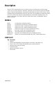
Description Spectra® IV IP was designed with ease of installation and ease of maintenance in mind. Each dome system consists of three components: a back box, a dome drive, and a lower dome. Spectra IV IP back box options include the following models: environmental in-ceiling (ideal for outdoor soffits), indoor in-ceiling, standard and environmental pendant, heavy-duty, and stainless steel.
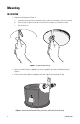
Mounting IN-CEILING 1. Prepare the ceiling (refer to Figure 1): a. Locate the center point of the mounting location, and insert the compass tool into the ceiling. b. Place the end of a pencil in the hole on the end of the compass tool, and draw a circle. c. Cut out the circle. Figure 1. Preparing the Ceiling 2. Attach a conduit fitting (not supplied), lock nut (not supplied), and safety chain bracket (refer to Figure 2). 3.
4. Open the hinged door to the back box by pushing the tab lock toward the wall of the unit and lifting the door open. 5. Pull the wiring into the back box through the conduit fitting. 6. Connect all required wiring (refer to Wiring on page 12). 7. Install the back box by compressing the spring clips and pushing the back box through the hole. 8. Tighten the screws until you hear a clicking noise. HEAVY-DUTY IN-CEILING 1. Prepare the ceiling (refer to Figure 1 on page 8): a.
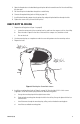
Figure 4. Installing the Plates ì Back Mounting Plates î Ceiling ï Mounting Ring 5. Attach a conduit fitting (not supplied), lock nut (not supplied), and safety chain bracket (refer to Figure 2 on page 8). 6. Install a safety chain/cable (not supplied), which will support up to 16 pounds (7.3 kg). 7. Open the hinged door to the back box by pushing the tab lock toward the wall of the unit and lifting the door open. 8. Pull the wiring into the back box through the conduit fitting. 9.
PENDANT, HEAVY-DUTY PENDANT, AND STAINLESS STEEL 1. Install the mount for the pendant dome. Refer to the instructions supplied with the mount. NOTE: If the mount is outdoors, make sure it is properly sealed to keep moisture out. 2. Open the hinged door to the back box by pushing the tab lock towards the wall of the unit and lifting the door open. 3. Pull the wiring into the back box. 4. Connect all required wiring (refer to Wiring on page 12). 5. Screw the back box onto the mount (refer to Figure 6).
Wiring 1. Open the hinged door to the back box by pushing the tab lock toward the wall of the unit and lifting the door open (refer to Figure 7). Figure 7.
2. Remove the TXB-N from the back box circuit board (refer to Figure 8): a. Loosen the captive screw on the TXB-N. b. Carefully unplug the TXB-N from the back box circuit board. +- Figure 8.
3. Connect the auxiliary, alarm, and other wiring to the back box circuit board (refer to Figure 9). NOTES: • • ALARMS AUX1 Aux 1: Maximum 2 A at low voltage (<40 V) Aux 2: Maximum 30 mA at 32 VDC If you are installing an environmental back box in a railway application, attach a ground wire from the circuit board power connector to a structural ground using at least 18-gauge wire. 1 2 3 4 5 6 7 GND NO COM NC AUX2 GND VIDEO PWR- GND PWR+ RX- RX+ TX- TX+ UTP+ UTP- Figure 9.
4. If you plan to use the audio functions, install your audio cables into the audio line-in and line-out connectors on the TXB-N. NOTES: • • To take full advantage of the distance and noise immunity benefits of audio, you must use a 600-ohm impedance matching transformer and twisted pair cable (refer to Figure 10). A stable power supply is required for optimal audio performance. Figure 10.
5. Reinstall the TXB-N: a. Plug the TXB-N into the 16-pin connector located on the back box circuit board. b. Secure the TXB-N to the standoff on the circuit board using the captive screw on the TXB-N. 6. Plug your network Ethernet cable into the RJ-45 connector on the TXB-N to connect the Spectra IV dome system to your existing network. WARNING: An electrical short in the back box may occur if the metal BNC connector on the video coaxial cable is not completely covered by the protective boot. 7.
Table A. Video Coaxial Cable Requirements Cable Type* Maximum Distance RG59/U 750 ft (229 m) RG6/U 1,000 ft (305 m) RG11/U 1,500 ft (457 m) *Cable requirements: • 75-ohm impedance • All-copper center conductor • All-copper braided shield with 95 percent braid coverage Refer to Table B for the recommended maximum distances for 24 VAC and 24 VDC applications, which are calculated with a 10 percent voltage drop. (Ten percent is generally the maximum allowable voltage drop for AC- or DC-powered devices.
Installing the Dome Drive 1. Perform one of the following options: • • View video using both analog and IP connections: Set the DIP switches on the top of the Spectra IV dome drive (refer to Figure 12). For DIP switch settings, refer to the labels located on the top of the dome drive, or refer to Switch Settings on page 28. View video using the IP connection: You do not need to set the DIP switches.
Installing the Lower Dome IN-CEILING 1. Snap the clip on the end of the trim ring leash into the hole on the lip of the back box (refer to Figure 13). Figure 13. Installing the In-Ceiling Lower Dome 2. Snap the trim ring into the plastic snap washers on the mounting screws.
HEAVY-DUTY IN-CEILING 1. Snap the clip of the lower trim ring leash into the hole on the lip of the back box (refer to Figure 14). 2. Insert both keys in the barrel locks. Turn the keys clockwise to the unlocked position. NOTE: Keys cannot be removed from the lock while in the unlocked position. 3. Align the ball studs, located on the mount ring, with the ball stud receivers, located on the inside of the lower dome. Push the lower dome into the back box. 4. Hold and turn both keys to the locked position.
PENDANT 1. Attach the back box leash to the lower dome (refer to Figure 15). Figure 15. Attaching the Leash to the Pendant Lower Dome 2. Push the lower dome into the back box. 3. Tighten the captive Phillips pan head screws to secure the lower dome. Figure 16.
HEAVY-DUTY PENDANT 1. Attach the back box leash to the lower dome (refer to Figure 15 on page 21). 2. Lightly apply O-ring lubricant (supplied with the lower dome) to the O-ring, and then install the O-ring in the groove on the trim ring of the lower dome (refer to Figure 17). Figure 17. Installing the O-Ring 3. Align the barrel locks in the lower dome with the holes located on each side of the back box (refer to Figure 18 on page 23). 4. Push the lower dome into the back box. 5.
Figure 18.
STAINLESS STEEL 1. Attach the back box leash to the lower dome using the nearest retainer screw (refer to Figure 19). Figure 19. Attaching the Leash to the Stainless Steel Lower Dome ì Leash î Retainer Screw 2. Lightly apply O-ring lubricant (supplied with the lower dome) to the O-ring, and then install the O ring in the groove on the trim ring of the lower dome (refer to Figure 17 on page 22). 3.
4. Push the lower dome into the back box, line up the mounting screw holes, and install the two mounting screws (refer to Figure 20). Figure 20.
Troubleshooting To use your dome, refer to the operation and configuration manual. If the following instructions fail to solve your problem, contact Pelco Product Support at 1-800-289-9100 (USA and Canada) or +1-559-292-1981 (international) for assistance. Be sure to have the serial number available when calling. Do not try to repair the unit yourself. Leave maintenance and repairs to qualified technical personnel only. Table C.
Table C. Troubleshooting the Spectra IV IP Dome System (2 of 2) Problem Possible Causes Suggested Resolution There is an echo when audio is received. The speaker volume is too high. Lower the speaker volume. The microphone and the speaker are too close together. If your call station does not have built-in echo cancellation, move the microphone and speaker farther apart. Your call station does not have built-in echo cancellation. Use a call station with built-in echo cancellation.
Switch Settings WARNING: If you are using Pelco D-type or Pelco P-type control, your system may not operate if the baud rate and address switches are not set correctly. The switches are set at the factory using the defaults for Pelco D-type control (2400 baud and address 1). Table D. Switch Settings for SW2 Special Systems Switch Number AD-32 Preset System 1 3 4 5 6 7 8 9 10 ON CM9502 Setting Vicon™ 2 ON Not currently available; SW2-3 is reserved for future use.
Table E. Switch Settings for SW1, Pelco P-Type Control NOTE: For Coaxitron controls, SW1 is not used; set all switches to OFF. For Pelco D-type control systems, refer to Table F on page 30.
Table F. Switch Settings for SW1, Pelco D-Type Control NOTE: For Coaxitron controls, SW1 is not used; set all switches to OFF. For Pelco P-type control systems, refer to Table E on page 29.
SWITCH SETTING SPECTRA ADDRESS SW1-1 SW1-2 SW1-3 SW1-4 SW1-5 SW1-6 SW1-7 SW1-8 38 OFF ON ON OFF OFF ON OFF OFF 39 ON ON ON OFF OFF ON OFF OFF 40 OFF OFF OFF ON OFF ON OFF OFF 41 ON OFF OFF ON OFF ON OFF OFF 42 OFF ON OFF ON OFF ON OFF OFF 43 ON ON OFF ON OFF ON OFF OFF 44 OFF OFF ON ON OFF ON OFF OFF 45 ON OFF ON ON OFF ON OFF OFF 46 OFF ON ON ON OFF ON OFF OFF 47 ON ON ON ON OFF ON OFF OFF 48 OFF OFF OFF
SPECTRA ADDRESS 32 SWITCH SETTING SW1-1 SW1-2 SW1-3 SW1-4 SW1-5 SW1-6 SW1-7 SW1-8 79 ON ON ON ON OFF OFF ON OFF 80 OFF OFF OFF OFF ON OFF ON OFF 81 ON OFF OFF OFF ON OFF ON OFF 82 OFF ON OFF OFF ON OFF ON OFF 83 ON ON OFF OFF ON OFF ON OFF 84 OFF OFF ON OFF ON OFF ON OFF 85 ON OFF ON OFF ON OFF ON OFF 86 OFF ON ON OFF ON OFF ON OFF 87 ON ON ON OFF ON OFF ON OFF 88 OFF OFF OFF ON ON OFF ON OFF 89 ON OFF OFF
SWITCH SETTING SPECTRA ADDRESS SW1-1 SW1-2 SW1-3 SW1-4 SW1-5 SW1-6 SW1-7 SW1-8 120 OFF OFF OFF ON ON ON ON OFF 121 ON OFF OFF ON ON ON ON OFF 122 OFF ON OFF ON ON ON ON OFF 123 ON ON OFF ON ON ON ON OFF 124 OFF OFF ON ON ON ON ON OFF 125 ON OFF ON ON ON ON ON OFF 126 OFF ON ON ON ON ON ON OFF 127 ON ON ON ON ON ON ON OFF 128 OFF OFF OFF OFF OFF OFF OFF ON 129 ON OFF OFF OFF OFF OFF OFF ON 130 OFF ON OFF O
SPECTRA ADDRESS 34 SWITCH SETTING SW1-1 SW1-2 SW1-3 SW1-4 SW1-5 SW1-6 SW1-7 SW1-8 161 ON OFF OFF OFF OFF ON OFF ON 162 OFF ON OFF OFF OFF ON OFF ON ON 163 ON ON OFF OFF OFF ON OFF 164 OFF OFF ON OFF OFF ON OFF ON 165 ON OFF ON OFF OFF ON OFF ON 166 OFF ON ON OFF OFF ON OFF ON 167 ON ON ON OFF OFF ON OFF ON 168 OFF OFF OFF ON OFF ON OFF ON 169 ON OFF OFF ON OFF ON OFF ON 170 OFF ON OFF ON OFF ON OFF ON 171 ON
SWITCH SETTING SPECTRA ADDRESS SW1-1 SW1-2 SW1-3 SW1-4 SW1-5 202 OFF ON OFF ON OFF OFF ON ON 203 ON ON OFF ON OFF OFF ON ON 204 OFF OFF ON ON OFF OFF ON ON 205 ON OFF ON ON OFF OFF ON ON 206 OFF ON ON ON OFF OFF ON ON 207 ON ON ON ON OFF OFF ON ON 208 OFF OFF OFF OFF ON OFF ON ON 209 ON OFF OFF OFF ON OFF ON ON 210 OFF ON OFF OFF ON OFF ON ON ON SW1-6 SW1-7 SW1-8 211 ON ON OFF OFF ON OFF ON 212 OFF OFF ON
SPECTRA ADDRESS 36 SWITCH SETTING SW1-1 SW1-2 SW1-3 SW1-4 SW1-5 SW1-6 SW1-7 SW1-8 243 ON ON OFF OFF ON ON ON ON 244 OFF OFF ON OFF ON ON ON ON 245 ON OFF ON OFF ON ON ON ON 246 OFF ON ON OFF ON ON ON ON 247 ON ON ON OFF ON ON ON ON 248 OFF OFF OFF ON ON ON ON ON 249 ON OFF OFF ON ON ON ON ON 250 OFF ON OFF ON ON ON ON ON 251 ON ON OFF ON ON ON ON ON 252 OFF OFF ON ON ON ON ON ON 253 ON OFF ON ON ON ON
Specifications ELECTRICAL (Dome Drive Only) Input Voltage Input Power 24 VAC 24 VDC 18 to 32 VAC; 24 VAC nominal 22 to 27 VDC; 24 VDC nominal 23 VA nominal (indoor, without heater) 73 VA nominal (outdoor, with heater) 0.7 A nominal (indoor, without heater) 3 A nominal (outdoor, without heater) Fuse 1.
IN-CEILING Construction Back Box Dome Drive Lower Dome Plastic Aluminum, thermoplastic Acrylic Cable Entry (Back Box) 0.75-inch conduit fitting Pan Movement 360° continuous pan rotation Vertical Tilt Unobstructed +2° to –92° Manual Pan/Tilt Speeds* Pan Tilt 0.1° to 80°/sec manual operation, 150°/sec turbo 0.
HEAVY-DUTY IN-CEILING Construction Back Box Dome Drive Lower Dome Aluminum Aluminum, thermoplastic Clear polycarbonate, 0.090-inch thick Cage Thickness 0.12 x 0.30-inch cast stainless steel Cage Color Black, for maximum discreetness Cable Entry (Back Box) 0.75-inch conduit fitting Pan Movement 360° continuous pan rotation Vertical Tilt +2° to –92° Manual Pan/Tilt Speeds* Pan Tilt 0.1° to 80°/sec manual operation, 150°/sec turbo 0.
PENDANT Construction Back Box Dome Drive Lower Dome Aluminum Aluminum, thermoplastic Acrylic Cable Entry (Back Box) Through 1.5-inch NPT pendant mount Pan Movement 360° continuous pan rotation Vertical Tilt Unobstructed +2° to –92° Manual Pan/Tilt Speeds* Pan Tilt 0.1° to 80°/sec manual operation, 150°/sec turbo 0.
HEAVY-DUTY PENDANT Construction Back Box Dome Drive Lower Dome Aluminum Aluminum, thermoplastic Clear polycarbonate, 0.09-inch thick Cage Thickness 0.12 x 0.30-inch cast stainless steel Cage Color Black, for maximum discreetness Cable Entry (Back Box) Through 1.5-inch NPT pendant mount Pan Movement 360° continuous pan rotation Vertical Tilt +2° to –92° Manual Pan/Tilt Speeds* Pan Tilt 0.1° to 80°/sec manual operation, 150°/sec turbo 0.
STAINLESS STEEL Construction Back Box Dome Drive Lower Dome Trim Ring Bubble 316 stainless steel; gray, polyurethane powder-coated finish Aluminum, thermoplastic 316 stainless steel; black, polyurethane powder-coated finish Acrylic, clear or smoked Cable Entry (Back Box) Through 1.5-inch NPT pendant mount Pan Movement 360° continuous pan rotation Vertical Tilt Unobstructed +2° to –92° Manual Pan/Tilt Speeds* Pan Tilt 0.1° to 80°/sec manual operation, 150°/sec turbo 0.
PRODUCT WARRANTY AND RETURN INFORMATION WARRANTY Pelco will repair or replace, without charge, any merchandise proved defective in material or workmanship for a period of one year after the date of shipment.
www.pelco.com Pelco, Inc.