® DD14 Series Intercept® Dome Drive Installation/ Operation Manual C458M-B (1/98) Pelco • 3500 Pelco Way, Clovis • CA 93612-5699 USA • www.pelco.
CONTENTS Section Page 1.0 GENERAL .................................................................................................. 5 1.1 IMPORTANT SAFEGUARDS AND WARNINGS ............................... 5 1.2 UNPACKING INSTRUCTIONS .......................................................... 6 2.0 DESCRIPTION .......................................................................................... 7 2.1 MODELS ............................................................................................
LIST OF ILLUSTRATIONS Figure 1 2 3 4 5 6 7 8 9 10 11 12 Page Back Box and Dome Drive Components ........................................... 9 Camera/Lens Wiring Diagram ........................................................... 10 Attaching Camera/Lens to Tilt Table ................................................. 11 Pan Limit Stops (Only Two Shown) ................................................... 12 24 VAC Back Box Wiring Diagram (For Dome Drives with Integral Receiver/Driver) .......................
(This page intentionally left blank.
1.0 GENERAL 1.1 IMPORTANT SAFEGUARDS AND WARNINGS Prior to installation and use of this product, the following WARNINGS should be observed. 1. Installation and servicing should only be done by Qualified Service Personnel and conform to all Local codes. 2. Unless the unit is specifically marked as a NEMA Type 3, 3R, 3S, 4, 4X ,6 or 6P enclosure, it is designed for Indoor use only and it must not be installed where exposed to rain and moisture. 3. Only use replacement parts recommended by Pelco. 4.
1.2 UNPACKING INSTRUCTIONS Unpack and inspect all parts carefully. Be sure to save the shipping carton and any inserts. They are the safest material in which to make future shipments. If an item appears to have been damaged in shipment, replace it properly in its carton and contact the factory a t 1-800-289-9100 or 1-559-292-1981 for a replacement. (International customers fax 1-559-348-1120 for authorization and instructions.
2.0 DESCRIPTION The DD14 Series of dome drives is part of the IDS14 Intercept® Series of domes. The IDS14 Series is an integral system that includes a back box (BB14), dome drive (DD14), and dome receiver/driver (DRD14). This manual covers the DD14 Series of dome drives. For installation and operation instructions for the back box, refer to manual C454M-C; for the dome receiver/ driver, refer to 466M-E. 2.
3.0 INSTALLATION Proceed with the installation of the dome drive after you have installed the back box. If a camera/lens package has not been installed on your dome drive, you can install the camera/lens either before you install the dome drive in the back box or after you install the dome drive. If you want to install the camera/lens first, proceed to Sections 3.2, LENS WIRING, and 3.3, CAMERA/LENS INSTALLATION, then return to Section 3.1, DOME DRIVE INSTALLATION. 3.1 DOME DRIVE INSTALLATION 1.
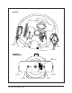
BACK BOX HAIRPIN CLIP LATCH GUIDE PIN HAIRPIN CLIP GUIDE PIN LATCH 25-PIN CONNECTOR DOME DRIVE UPPER BRACKET 25-PIN CONNECTOR LATCH PIN LATCH PIN BUSHING BUSHING Figure 1.
Figure 2.
3.3 CAMERA/LENS INSTALLATION Install the camera/lens you have selected for use with the IDS14 series dome as follows: 1. Loosen the 1/4-20 lens support fastener (item 1 in Figure 3) and slide lens support down. 2. Attach camera/lens to the tilt table with the 1/4-20 x 3/4" bolt, flat washer, and lock washer (items 2 in Figure 3) that are provided. If the camera/lens can be balanced on the tilt table, the life of the dome drive will be extended. 3.
NOTE: The tilt limit stops are not 3. adjustable. Models with 355° Rotation Only - Adjust the pan limit stops: a. Pan the unit to the desired left position. b. Turn off the power. c. Position the limit stop and tighten it in place. Refer to Figure 4 for the location of the limit steps. Disconnect the drive from the back box, if necessary, to make the adjustment. CAUTION: Do not re- To remove the dome drive: move or reposition the fixed limit stop. Damage will occur. 1. 2. 3. 4.
4.0 MAINTENANCE Regularly scheduled maintenance will prolong the operational life and appearance of the equipment. Clean the dome with a nonabrasive cleaning cloth and antistatic cleaner that is safe for use on acrylic plastic. Do not use kerosene or similar substances that can scratch the surface. The dome drive should also be inspected and any dust and debris blown off. Pay special attention to the spur gear drives.
5.0 WIRING DIAGRAMS Figure 5.
Figure 6.
Figure 7.
Figure 8.
Figure 9.
Figure 10.
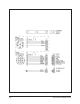
6.0 EXPLODED ASSEMBLY DIAGRAMS 1 2 3 4 8 5 49 10 6 11 7 12 39 47 13 48 14 25 46 36 45 40 44 41 42 9 24 22 21 23 50 61 15 43 19 36 38 28 60 56 65 27 31 29 REMOVE BEFORE OPERATING 26 30 16 34 20 17 18 51 52 54 55 33 53 32 Figure 11.
Table A.
Table A (continued) Item Quantity 40 41 42 43 44 45 46 47 48 49 50 51 52 53 54 55 56 2 1 1 1 1 1 1 1 2 3 1 1 1 1 1 1 1 57 58 1 1 59 9 60 61 62 63 64 65 1 1 1 1 1 1 66 1 1 22 Description Sealed bearing Wave spring Boss, bearing, tilt Encoder, preset tilt (preset models only) Gear, preset tilt (preset models only) Encoder, preset pan (preset models only) Bracket, pan preset encoder (preset models only) Gear, pan preset encoder (preset models only) Snap ring (355° models only) Spindle stand-off L
Q O F N E F D N N BB C V G H X L CC N N L I Z P L U N J AA N J W K B R L T P N N L L N Q DD Y V M S N N N N L L L L L N A L N B N EE L Figure 12.
Table B. DD14 Series Dome Drive Exploded Assembly Hardware Parts List (Figure 12) Item Quantity A B 4 C D E F G H I J K L M N 24 14 10 2 2 2 5 3 2 6 2 5 8 4 33 3 O P Q R S 47 43 3 2 11 8 3 T U V W X Y Z 1 1 2 4 1 8 1 AA BB CC 4 2 4 DD EE 1 8 Description Part Number Spacer, 1/4" O.D.
7.0 SPECIFICATIONS MECHANICAL Pan: Movement in horizontal plane: 0-355° with pan limit stops 360° without pan limit stops Tilt: -90° movement from horizontal plane Pan and Tilt Speeds: The following speeds are available and pre-selected by customer at time of order: Dome Drive Type Motors: Pan Speed Tilt Speed DD14B1L DD14B1L-H DD14C1L DD14C1L-H DD14D1L 12°/sec ± 1° 6°/sec ±.5° DD14B2L DD14B2L-H DD14C2L DD14C2L-H DD14D2L DD14E2L 24°/sec ± 1° 12°/sec ±.
ELECTRICAL Power Requirements: Pan and Tilt Idle Variable Speed Unit All Others 24 vA 15 vA 7.5 vA 2.5 vA Maximum Current: 2 amps per conductor (360° models only) Camera Power: 24 VAC Limit Switches Pan: 5 amp, external adjustment (355° models only) Tilt: 5 amp (factory set) GENERAL Construction Pan/Tilt: Aluminum with stainless steel hardware Dome Liner: Plastic Max. Weight: 10.7 lbs (4.85 kg). (Combined weight of dome drive with integral receiver/driver and dome.
NOTES Pelco Manual C458M-B (1/98) 27
8.0 WARRANTY AND RETURN INFORMATION WARRANTY Pelco will repair or replace, without charge, any merchandise proved defective in material or workmanship for a period of one year after the date of shipment. Exceptions to this warranty are as noted below: • Five years on FT/FR8000 Series fiber optic products. • Three years on Genex® Series products (multiplexers, server, and keyboard).