INSTALLATION/OPERATION WCS1-4 Environmental Power Supply C561M-F (8/06)
Important Safeguards and Warnings 1. Read these instructions. 2. Keep these instructions. 3. Heed all warnings. 4. Follow all instructions. 5. Installation should be done only by qualified service personnel and conform to all local codes. 6. Use only installation methods and materials capable of supporting four times the maximum specified load. 7. Do not install near any heat sources such as radiators, heat registers, stoves, or other apparatus (including amplifiers) that produce heat. 8.
Description The WCS1-4 is a single power supply designed for indoor or outdoor applications and is ideal for use with cameras, domes, and integrated positioning systems such as Spectra® and Esprit®. The WCS1-4 power supply has one fused output and is capable of handling up to 4 amps (100 VA) of total load. The unit features selectable 100/120/240 VAC input power, selectable 24/26/28 VAC output power, and a stainless steel link-lock latch that can be secured with padlock (padlock not provided).
Installation MOUNTING INSTRUCTIONS To mount the power supply directly to a wallboard, wall, or concrete refer to Figure 1 through 3 and do the following: 1. Remove the retaining screw from the door latch of the WCS1-4 power supply. 2. Open the door of the WCS1-4 power supply, and then remove the plug(s) from the required conduit hole(s) located on the bottom of the unit. Install 3/4-inch (1.91 cm) conduit fitting(s) (not supplied). Close the lid to the power supply. 3.
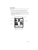
FUSE INSTALLATION The WCS1-4 power supply is shipped from the factory with a 1.6-amp fuse installed for 100/120 VAC input power. To use input power of 240 VAC, change the 1.6-amp fuse to a 500-milliamp fuse (supplied). To change the fuse remove the lid to the fuse holder (refer to Figure 4) located inside the power supply and then install the new fuse. Store extra fuses (supplied) in the spare fuse holders. INPUT POWER WIRING WARNING: The WCS1-4 does not have an on/off switch.
OUTPUT WIRING To install the output wiring to the camera, dome, or positioning system, refer to Figure 4 and do the following: 1. Refer to Table A and determine the output connection needed for your camera, dome, or positioning system. Refer to Figure 4, for the proper connector strip connections. 2.
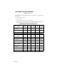
CABLE CONNECTIONS AND REQUIREMENTS Table A. Wiring Distances The following are the recommended maximum distances to wire the WCS1-4 to a Spectra III or Esprit positioning system. To determine the correct voltage tap: 1. Pick the unit type. 2. Find the wire gauge used (22 gauge is not recommended). 3. Determine which secondary output tap (A, B, or C) is appropriate for the distance between the dome or positioning system and the WCS1-4. Distance is in feet (meters).
Maintenance There are no user-serviceable parts except for the fuse. If the transformer in the WCS1-4 does not work properly, the entire environmental power supply needs to be returned to the factory for repair. Refer to the Warranty and Return Information for instructions on returning the WCS1-4. Clean the outer surface of the WCS1-4 box with a nonabrasive cleaning cloth and antistatic cleaner. Do not use kerosene or similar substances that may damage the surface.
Specifications ELECTRICAL Input Voltage Selectable 100, 120, 240 VAC, 50/60 Hz via the Primary Line Input connector strip Output Voltage/Power Selectable 24 VAC (Tap A), 26 VAC (Tap B), or 28 VAC (Tap C) at 100 VA via the Secondary Output Tap’s connector strip Fusing One fuse. Select from one of the following supplied fuses: Three 1.
7.32 (18.8) 7.65 (19.4) 6.63 (16.8) 6.71 (17.0) 4.50 (11.4) 4.01 (10.3) 6.50 (16.5) NOTE: VALUES IN PARENTHESES ARE CENTIMETERS; ALL OTHERS ARE INCHES. Figure 5. WCS1-4 Dimension Drawing The materials used in the manufacture of this document and its components are compliant to the requirements of Directive 2002/95/EC.
PRODUCT WARRANTY AND RETURN INFORMATION WARRANTY Pelco will repair or replace, without charge, any merchandise proved defective in material or workmanship for a period of one year after the date of shipment. Exceptions to this warranty are as noted below: • Five years on FR/FT/FS Series fiber optic products and TW3000 Series unshielded twisted pair transmission products. • Three years on Genex® Series products (multiplexers, server, and keyboard).
Worldwide Headquarters 3500 Pelco Way Clovis, California 93612 USA USA & Canada Tel: 800/289-9100 Fax: 800/289-9150 International Tel: 1-559/292-1981 Fax: 1-559/348-1120 www.pelco.