I N S T A L L A T I O N IS20/IS21 Series Camclosure® 2 Integrated Camera System Color and Day/Night Models Flush Mount, Surface Mount C3472M-C (9/10)
Contents Contents . . . . . . . . . . . . . . . . . . . . . . . . . . . . . . . . . . . . . . . . . . . . . . . . . . . . . . . . . . . . . . . . . . . . . . . . . . . . . 2 Important Safety Instructions. . . . . . . . . . . . . . . . . . . . . . . . . . . . . . . . . . . . . . . . . . . . . . . . . . . . . . . . . . . . . 3 UL Listed Models . . . . . . . . . . . . . . . . . . . . . . . . . . . . . . . . . . . . . . . . . . . . . . . . . . . . . . . . . . . . . . . . . 4 Warnings . . . . . . . . . . . . . .
Important Safety Instructions 1. Read these instructions. 2. Keep these instructions. 3. Heed all warnings. 4. Follow all instructions. 5. Do not use this apparatus near water. 6. Clean only with dry cloth. 7. Do not block any ventilation openings. Install in accordance with the manufacturer’s instructions. 8. Do not install near any heat sources such as radiators, heat registers, stoves, or other apparatus (including amplifiers) that produce heat. 9.
UL LISTED MODELS IS21-CHV10S IS21-CHV10F IS20-CHV10S IS20-CHV10F IS21-DNV10S IS21-DNV10F IS20-DNV10S IS20-DNV10F WARNINGS • • • • • This apparatus must be earthed. To prevent fire or electric shock hazard, do not expose this apparatus to rain or moisture. The apparatus should not be exposed to dripping or splashing and that no objects filled with liquids, such as vases, should be placed on the apparatus. The connections should comply with local electrical code.
8. Cleaning the camera body: • Turn the power off when cleaning the product. Use a dry cloth to clean the product. • Do not use strong abrasive detergent when cleaning the product body. When the dirt is hard to remove, use a mild detergent and wipe gently. Then, wipe off the remaining detergent with a dry cloth; otherwise, it may cause discolouration. • When using a chemical cloth for cleaning, read the caution provided with the chemical cloth product. 9.
We declare under our sole responsibility that the product to which this declaration relates is in conformity with the standards or other normative documents following the provisions of Directives 2006/95/EC and 2004/108/EC. Wij verklaren als enige aansprakelijke, dat het product waarop deze verklaring betrekking heeft, voldoet aan de volgende normen of andere normatieve documenten, overeenkomstig de bepalingen van Richtlijnen 2006/95/EC en 2004/108/EC.
Limitation of Liability THIS PUBLICATION IS PROVIDED “AS IS” WITHOUT WARRANTY OF ANY KIND, EITHER EXPRESS OR IMPLIED, INCLUDING BUT NOT LIMITED TO, THE IMPLIED WARRANTIES OF MERCHANTABILITY, FITNESS FOR ANY PARTICULAR PURPOSE, OR NON-INFRINGEMENT OF THE THIRD PARTY’S RIGHT. THIS PUBLICATION COULD INCLUDE TECHNICAL INACCURACIES OR TYPOGRAPHICAL ERRORS. CHANGES ARE ADDED TO THE INFORMATION HEREIN, AT ANY TIME, FOR THE IMPROVEMENTS OF THIS PUBLICATION AND/OR THE CORRESPONDING PRODUCT (S).
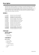
Description The IS20/IS21 Series Camclosure® 2 camera system integrates a camera and lens package into a small versatile indoor enclosure that can be mounted directly to, or recessed into, a ceiling or wall. The IS20/IS21 Series features a three-axis camera and lens positioning system that is capable of a wide variety of pan and tilt angles. The day/night models feature a high resolution (540 TVL) color camera with auto iris and varifocal lens.
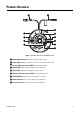
Product Overview (Day/night model shown) Figure 1. Product Overview of IS20-DN Camera ì Video Output Connector: Transmits composite video signals. î Power Cable: Supplies 24 V AC or 12 V DC from an external power source. ï Panning Table Lock Screw (LOCK): Fixes the panning table. ñ Panning Table: Adjusts the panning position of the camera. ó Tilting Table: Adjusts the tilting position of the camera. r Tilting Lock Screws (left and right): Fixes the tilting position.
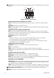
~í Dip Switch: Selects ON/OFF of white balance, backlight compensation, Adaptive Black Stretch or day/night mode. B.S. D/N BLC ATW ON OFF AWC Figure 2. Default Dip Switch Settings Simple day/night mode selector (D/N) for color models: ON: The camera selects black-and-white mode if the picture is dark, or color mode if the picture is bright enough. OFF (default): Color picture is displayed normally. NOTE: The simple day/night function is established by using the SENSE UP function for black-white images.
Installation The following installation should be performed by qualified service personnel or system installers. NOTES: • Procure 4 mounting screws according to the material of the installation area. In this case, wood screws and nails should not be used. • The recommended tightening torque is M4: 1.6 N·m (16 kgf·cm). • The required pullout capacity of a single screw/bolt is 196 N (20 kgf) or more.
b. Adjust the marker on this unit to “I” on the top cover, and turn the top cover counterclockwise to remove it (refer to Figure 5). NOTE: The dome cover and the inner dome cover are joined into a single unit; therefore, never try to remove them. Figure 5.
MOUNTING THE CAMERA The mounting requirements are shown as follows: Mounting Site Recommended Screw and Number of Minimum Pullout Tightening Torque Screws Strength Model Ceiling/wall Two-gang junction M4 (or appropriate), box 4 pcs. 196 N/pc.(20 kgf/pc.) 1.6 N·m (16 kgf·cm) Ceiling/wall Surface mount M4 (or appropriate), 1.6 N·m (16 kgf·cm) 4 pcs. 196 N/pc.(20 kgf/pc.
SURFACE MOUNTING 1. Prepare the mounting space. • • If the camera is directly mounted on a wall/ceiling, align the camera mounting position with the position of the hole through which the cables are routed, and then make the hole. If no hole is made through a wall/ceiling and open wiring along a wall/ceiling is used, remove the dust guard cap, take out the cable, replace the dust guard cap, and then process the cover so that the cables can be routed through the side of the cover. 2.
3. Attach the ceiling mount bracket onto the ceiling board (refer Figure 8). NOTE: Maximum thickness of the ceiling board is 30 mm (1.18 inches) for installation. Loosen the clamping screws until the length between the clamp plates becomes wider than the thickness of the ceiling board, and then clamp the ceiling board by tightening the clamping screws. The recommended tightening torque is 0.61 N·m (6.0 kgf·cm). Figure 8.
WIRING Figure 9. Video Output Connector and Power Cable ì Video Output Connector î Power Cable VIDEO OUTPUT CONNECTION NOTE: When connecting the coaxial cable to the video output connector, make sure that the connector of the coaxial cable is locked firmly. Connect the video output connector to the monitor, or other system devices, with coaxial cable (not supplied). Table A.
POWER CONNECTION Connect the 3-conductor cable of the camera to the power supply. Table B. Power Wire Colors and Functions Wire Color 12 V DC 24 V AC Brown Positive Live Blue Negative Neutral Green/yellow — Grounding Figure 10. Power Cable WARNINGS: • Be sure to connect the GND (grounding) lead of the camera and grounding terminal of the power supply when using a 24 V AC power source. • Only connect this product to a 24 V AC or 12 V DC Class 2 power supply.
CABLE LENGTH AND WIRE GAUGE 24 V AC The voltage supplied to the power terminals of the camera should be within 19.5 V AC and 28 V AC. Table C. 24 V AC Recommended Cable Length and Thickness Copper Wire Size (AWG) #24 (0.22 mm2) #22 (0.33 mm2) #20 (0.52 mm2) #18 (0.83 mm2) 20 30 45 75 (m) Length of Cable (approx.) 12 V DC Use the formula below to calculate the power cable and power supply. The voltage supplied to the power terminals of the camera should be within 10.8 V DC and 16 V DC. Table D.
IMAGE ADJUSTMENT PAN, TILT, AND AZIMUTH ADJUSTMENT WARNINGS: • Do not touch the iris motor. • Do not hold the camera by the lens unit when adjusting pan, tilt, or azimuth. 1. Rotate the panning table (320-degree range) to adjust the panning position of the camera (refer to Figure 11). The adjusting range is from +180 degrees (clockwise) to –140 degrees (counterclockwise). 2. Tighten the panning table lock screw. 140° 180° Figure 11.
3. Rotate the tilting table (±75-degree range) to adjust the tilting position of the camera (refer to Figure 12). NOTES: • • This lens can also be rotated in the reverse direction, but the image azimuth is reversed. In such a case, turn the panning table to the 180-degree side to correct the azimuth image. When used at an angle that is close to horizontal, the shadow of the dome cover may be projected. 75° 75° Figure 12. Adjusting the Tilting Position (Day/Night Model Shown) ì Tilting Lock Screw 4.
ZOOM AND FOCUS ADJUSTMENT 1. Loosen the zoom lock lever and move the lever between TELE and WIDE to obtain the appropriate angle of view (refer to Figure 14). 2. Tighten the zoom lock lever. 3. Loosen the focus lock lever and move the lever between FAR and NEAR to obtain the optimum focus. 4. Tighten the focus lock lever. NOTE: You can change the angle of view by moving the zoom lock lever, and you can move the focus lock lever to adjust the focus. Figure 14.
ASSEMBLING THE CAMERA 1. Mount the top cover (refer to Figure 15): a. Adjust the marker of this unit to “I” on the top cover to install the top cover. Figure 15. Mounting the Top Cover ì Marker î Top Cover ï Dome Cover Block b. 22 Rotate the top cover clockwise to adjust the marker to “II.
c. Turn the dome cover block to the right and left while watching the monitor. Make adjustments so that no eclipse is caused. WARNING: If the dome cover block is moved with unreasonable force, it may break. d. Rotate the top cover clockwise to adjust the marker to “III.” 2. Secure the top cover and the camera main unit with an accessory fixing screw (M3). Figure 16.
3. (Flush mount models only) Attach the supplied flush mount cover: a. Match the logos on the cover and on the main body of the camera. b. Pull out both of the spring hooks and attach the hooks to the cover. c. Make sure that the cover is attached to the ceiling with no space between them. Figure 17.
Specifications Power Source and Consumption PAL NTSC Image Sensor Effective Pixels PAL NTSC Scanning Area Scanning System Scanning Lines PAL NTSC Scanning Frequency Horizontal Vertical Synchronization Resolution Horizontal Vertical Video Output White Balance Signal-to-Noise Ratio Minimum Illumination at F1.
(Weights and dimensions indicated are approximate.) 1.81 (4.60) 0.18 (0.45) Ø 0.16-0.18 (0.40-0.45) 3.29 (8.35) Ø 5.10 (12.95) 1.89 (4.80) 3.66 (9.30) 5.10 (12.95) Ø 1.18-1.97 (3.00-5.00) Ø 1.58 (4.00) 2.36 (6.00) 1.97 (5.00) 0.30 (0.75) MAX 1.18 (3.00) 7.32 (18.60) Ø 1.58 (4.00) HOLE IN THE CEILING Ø 6.30 (16.00) NOTE: VALUES IN PARENTHESES ARE CENTIMETERS; ALL OTHERS ARE INCHES.
PRODUCT WARRANTY AND RETURN INFORMATION WARRANTY Pelco will repair or replace, without charge, any merchandise proved defective in material or workmanship for a period of one year after the date of shipment.
www.pelco.com Pelco, Inc.