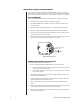
® 01215 MRD1400HZ16 Camera Control Interface for the CC1400HZ16 Installation/ Operation Manual C1973M-B (8/03) Pelco • 3500 Pelco Way • Clovis, CA 93612-5699 USA • www.pelco.
CONTENTS Section Page IMPORTANT SAFEGUARDS AND WARNINGS ................................................................ 3 DESCRIPTION ................................................................................................................... 4 INSTALLATION .................................................................................................................. 4 DIP SWITCH SETTINGS ...........................................................................................
IMPORTANT SAFEGUARDS AND WARNINGS Prior to installation and use of this product, the following WARNINGS should be observed. 1. Installation and servicing should only be done by qualified service personnel and conform to all local codes. 2. There are no user-serviceable parts inside this unit. Only authorized service personnel may open the unit. 3. To reduce the risk of fire or electric shock, do not expose this unit to rain or moisture if this unit is designed for indoor use only.
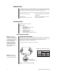
DESCRIPTION The MRD1400HZ16 is a camera interface control for Pelco’s CC1400HZ16 Series digital color camera. The unit can be mounted directly to a wall or installed in a DF5 Series dome, DF8A Series dome, EH2512 Series enclosure, or EH3512 Series enclosure.
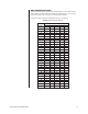
MRD ADDRESS SETTINGS A camera address setting is required for the controller/switcher to communicate with the MRD1400HZ16. The default setting for the MRD is Receiver Address 1. If you are using more than one MRD, each unit must have a different Receiver Address. To change the address setting of the MRD, refer to Figure 1 and Table B. Table B.
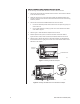
MRD1400HZ16 INSTALLATION METHODS There are three methods of installation for the MRD1400HZ16. The unit can be mounted directly to a wall, or installed inside a dome or enclosure using the supplied mount adapters. Refer to the following sections and select the correct installation method for your application. WALL MOUNTING To mount the MRD1400HZ16 directly to a wall, refer to Figure 2 and do the following: 1. Select the mounting location. Install the unit close to the camera. 2.
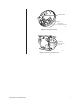
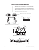
CAMERA BRACKET DOME MRD1400HZ16 AND MOUNT ADAPTER 01212 Figure 3. DF5/DF8 Installation POWER LED RESET BUTTON DATA LED 01216 Figure 4.
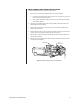
EH3512 SERIES ENCLOSURE INSTALLATION Do the following to install the MRD1400HZ16 in an EH3512 Series enclosure: 1. Remove the camera sled from the EH3512 Series enclosure. If the camera is attached to the sled remove the camera. 2. Attach the camera to the 4-inch camera sled supplied with the MRD. Install the camera sled and camera into the enclosure. Place the camera sled as close to the viewing window as possible. 3. Remove the PC board from the MRD1400HZ16. To remove the board: a.
EH2512 SERIES ENCLOSURE INSTALLATION To install the MRD1400HZ16 in an EH2512 Series enclosure: 1. Remove the PC board from the MRD1400HZ16. To remove the board: a. Unscrew the two Phillips button head screws from the unit (refer to Figure 2), and remove the cover. Discard the screws. b. Using a small screwdriver, carefully pry each corner of the board from the PEM studs. Refer to Figure 4. 2.
CONTROL, POWER, AND CAMERA CONNECTIONS 1. Refer to Figure 8 and Table C. Connect the control wires from the controller to the MRD DATA IN connector. Use the supplied four-pin connector. To connect multiple units with parallel connections refer to Figure 9. 2. Connect one end of the 12-inch data cable into the CAM input of the MRD (refer to Figure 8). Connect the other end of the cable to the camera connector labeled CONTROL OUT. If the installation requires a longer data cable refer to Figure 10.
OPERATION CAMERA OPERATION PELCO CONTROLLER COMMAND Zoom In Tilt joystick up Zoom Out Tilt joystick down Quickly Zoom In Press the Zoom Tele button or turn the joystick clockwise Quickly Zoom Out Press the Zoom Wide button or turn the joystick counterclockwise Focus Near Press the Focus Near button Focus Far Press the Focus Far button Increase Brightness Press the Iris Open button Decrease Brightness Press the Iris Close button Enter/Exit the camera menu *Preset 95 or AUX 8 ON Navigate t
TROUBLESHOOTING Problem Possible Cause and Solutions Unit does not operate. No power. 1. Check to see if the power LED is lit. If the LED is not lit: a. Verify input power is good. b. Check power connections to make sure the wires are making contact. c. Verify the input power source is in range 12-24 volts AC/DC. Camera does not respond or responds improperly to commands. 1. Check the baud rate of the MRD and the controller/switcher. Both should have the same baud rate setting. 2.