
User's Manual


10 Pelco Manual C1973M-B (8/03)
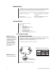
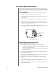
CONTROL, POWER, AND CAMERA CONNECTIONS
1. Refer to Figure 8 and Table C. Connect the control wires from the controller to the
MRD DATA IN connector. Use the supplied four-pin connector. To connect multiple
units with parallel connections refer to Figure 9.
2. Connect one end of the 12-inch data cable into the CAM input of the MRD (refer to
Figure 8). Connect the other end of the cable to the camera connector labeled CON-
TROL OUT. If the installation requires a longer data cable refer to Figure 10. Maximum
cable length is 25-feet.
3. Make required power connections. Refer to Figure 8.
Table C. Two-Wire Control Connections
From
Controller MRD
TX+ R+
TX- R-
DATA
IN
RST
DATA
CAM
P
W
R
SW1
MRD1400HZ16
Made in USA
T+
T-
R-
R+
(+)
(-)
NO CONNECT
01219
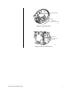
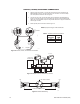
Figure 8. Control, Power, and Camera Connections
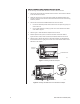
Figure 9. Multiple Units with Parallel Connections
1
2
3
4
5
6
7
8
8
7
6
5
4
3
2
1
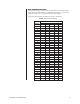
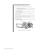
PIN
PIN
LOCKING TAB ON BOTTOM
ONE TWIST IN CABLE
01221
Figure 10. Data Cable Wiring
Note:
Input power range 12-24 volts AC/DC.
R+ R-T+ T-
MRD
CC1400HZ16
CC1400HZ16
CC1400HZ16
FROM THE
CONTROLLER
Tx+
Tx-
R+ R-T+ T-
MRD
R+ R-T+ T-
MRD