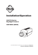
Installation/Operation CC3770 Series Day/Night Camera C2915M-E (08/05) Pelco Worldwide Headquarters • 3500 Pelco Way, Clovis, CA 93612-5699 USA • www.pelco.
® Pelco, the Pelco logo, Spectra, Genex, Legacy, Esprit and Camclosure are registered trademarks of Pelco. ™Endura and ExSite are trademarks of Pelco ™DLP is a trademark of Texas Instruments, Inc. ™SuperHAD CCD is a trademark of the Sony Corporation. © Copyright 2005, Pelco. All rights reserved.
CONTENTS IMPORTANT SAFETY INSTRUCTIONS .......................................................................................................... 4 REGULATORY NOTICES ................................................................................................................................. 5 DESCRIPTION ................................................................................................................................................... 6 Models ............................................
IMPORTANT SAFETY INSTRUCTIONS 1. 2. 3. 4. 5. 6. 7. 8. 9. 10. 11. 12. 13. 14. 15. 16. 17. 18. 19. 20. 21. 22. Read these instructions. Keep these instructions. Heed all warnings. Follow all instructions. Do not use this apparatus near water. Clean only with dry cloth. Do not block any ventilation openings. Install in accordance with the manufacturer’s instructions. Do not install near any heat sources such as radiators, heat registers, stoves, or other apparatus (including amplifiers) that produce heat.
REGULATORY NOTICES This device complies with Part 15 of the FCC Rules. Operation is subject to the following two conditions: (1) this device may not cause harmful interference, and (2) this device must accept any interference received, including interference that may cause undesired operation. RADIO AND TELEVISION INTERFERENCE CC3770H-6 and CC3770H-6X models: This equipment has been tested and found to comply with the limits of a Class B digital device, pursuant to Part 15 of the FCC Rules.
DESCRIPTION CC3770 Series cameras are day/night, color/black-white switching video cameras with a 1/3-inch CCD imager. All cameras have a direct drive/auto iris lens connector and adjustable back focus, and they accept C and CS lenses. Models CC3770H-6 High resolution (480 color/530 b-w TV lines), SuperHAD™ CCD, 0.7 lux at F1.2 in color mode, 0.09 lux at F1.2 in black-white mode, NTSC, 12 VDC/24 VAC CC3770H-6X High resolution (480 color/530 b-w TV lines), SuperHAD™ CCD, 0.7 lux at F1.2 in color mode, 0.
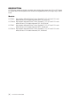
CAMERA LAYOUT Figure 1. Camera Layout INSTALLATION Lens Mounting The CC3770 Series camera can use fixed iris, manual iris, auto iris, or direct drive lenses. Automatic day/night operation is optimized for use with auto-iris lenses. Cameras are factory-set for CS-mount lenses, but are easily adjusted for C-mount lenses. 1. C-Mount Lens Only - Loosen the two back focus locking screws.
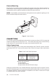
Camera Mounting Mounting points are provided on the top and bottom of the camera and are used to mount the camera on a bracket or tripod. They are designed to accept standard photographic mounting bolts (1/4-inch UNC-20). The mounting bracket must be capable of supporting the weight of the camera and its lens. NOTE: Some installation codes dictate that the mounting bracket must be capable of supporting up to four times the combined weight of the camera and lens. Figure 3.
Power Connections CC3770 Series cameras are available in AC high voltage and AC/DC low voltage types. The voltage required to operate the camera is clearly marked on the rear panel of the camera. The green POWER LED on the rear panel indicates that power is connected. Power low voltage cameras only from a UL Listed Class 2 isolated power supply. Power consumption is 6 watts.
Table B. Wiring Distances for 5 VA Cameras (24 VAC/12 VDC) The following are the recommended maximum distances for low voltage cameras. These distances are calculated with a 10 percent voltage drop. (Ten percent is generally the maximum allowable voltage drop for AC-powered devices.) Wire Gauge 24 VAC 12 VDC AWG mm2 Feet Meters Feet Meters 24 22 20 18 16 14 12 10 0.25 0.35 0.5 1 1.5 2.
Color/Black-White Switching CC3770 Series cameras can switch between color and black-white operation automatically or via an external switching device. By default, this switching will occur automatically. When the camera is powering up, it defaults to black-white mode. After 10 seconds, the camera switches to color mode.
RJ45-10 Connections The RJ45-10 connector allows video (composite and twisted pair) and power connections to be made to the camera using a single Cat5-style cable. NOTE: The PCM150 camera mount is designed for the CC3770 Series camera. It comes with preconfigured auxiliary connectors and cables as well as an easy-to-wire adapter plate. Before installation, identify the RJ45-10 connector leads to be used.
To send composite video through the RJ45-10 connector: 1. Connect composite video out to pin 3. 2. Connect composite video ground to pin 2. Manual Color/B-W Switch The camera can be switched between color and black-white operation manually using an external switching device. The remote switch should be connected to pin 4 and pin 7 and the switch must be connected in parallel with a 10 kΩ resistor as shown in Figure 4. The cable length must be no more than 1,000 feet (300 meters).
CAMERA SETUP Lens Setup and Focus Procedures Video Drive or Direct Drive (DC) Auto Iris Lens 1. Set the ESC switch and AGC switch to OFF. 2. Adjust the lens for the optimum picture. Video Drive - Refer to the lens instructions and adjust the lens for the optimum picture (video output level of 1 V peak-to-peak). Direct Drive - Use an appropriate screwdriver to turn the lens level potentiometer (refer to Figure 1) fully clockwise.
Back Focus Adjustment Before adjusting the back focus on a CC3770 camera equipped with an auto-iris lens, apply an external ND 3.0 filter. Using this filter drives the lens to its most open position, reducing the depth of field to its worst-case condition. The ND filter also attenuates the light levels so that the camera switches to night (black-white mode) after a delay of about 10 seconds.
Switch Settings Figure 9. Switch Settings (White indicates default switch position.) NOTE: Under most conditions, no setting of switches will be required. Please read the details of each switch before making any adjustments. AGC (Automatic Gain Control) - Switch Setting 1 Automatically adjusts the image to compensate for low levels of illumination. Choose between the following settings: ON (Default setting) - Enables the AGC mode. (Use this setting for automatic day/night operation).
Flickerless - Switch Setting 4 The flickerless setting can reduce the flicker caused by certain lighting conditions. The Electronic Shutter Control must be off for the correct operation of the flickerless function. Choose between the following settings: ON - Enables the Flickerless mode. OFF (Default setting) - Disables the Flickerless mode. INT/LL Synchronization Selection - Switch Setting 5 Line lock (LL) locks the frame rate to the power supply frequency.
Camera Synchronization When using more than one camera power supply, a brief vertical roll may occur on the monitor when a camera view is switched. To eliminate this vertical roll, it is necessary for the cameras to be synchronized. If the cameras are connected to certain Pelco matrix products, the cameras will automatically lock to the pulse signal that is transmitted up-the-coax. If not, it will be necessary to synchronize manually. Cameras can be line locked or synchronized internally.
SPECIFICATIONS GENERAL Day/Night Operation Day: Night: Imaging Device: Picture Elements NTSC: PAL: Sensing Area: Scanning System NTSC: PAL: Synchronization System: Horizontal Resolution: Iris Control: Electronic Shutter Range NTSC: PAL: Auto Iris Lens Type: Minimum Illumination Color Mode: Black-White Mode: Signal-to-Noise Ratio: Vertical Phase: Automatic Gain Control: Electronic Shutter Control: Backlight Compensation: Flickerless Mode: Internal Sync: Auto White Balance: D/N Dusk-Dark: Signal Processing: V
MECHANICAL Lens Mount: Camera Mount: C/CS mount (adjustable) 1/4-inch UNC-20 screw, top or bottom of camera housing ENVIRONMENTAL Operating Temperature: Storage Temperature: Operating Humidity: Storage Humidity: 32° to 122°F (0° to 50°C) 14° to 158°F (-10° to 70°C) 20% to 80%, non-condensing 20% to 90%, non-condensing PHYSICAL Dimensions: Weight (without lens): 5" L x 2.9" W x 2.6" H (12.8 x 7.2 x 6.7 cm) 0.8 lb (0.4 kg) (Design and product specifications subject to change without notice).
Pelco Manual C2915M-E (08/05) [ 21 ]
PRODUCT WARRANTY AND RETURN INFORMATION WARRANTY Pelco will repair or replace, without charge, any merchandise proved defective in material or workmanship for a period of one year after the date of shipment. Exceptions to this warranty are as noted below: • Five years on FT/FR8000 Series fiber optic products. • Three years on Genex® Series products (multiplexers, server, and keyboard).
REVISION HISTORY Manual # C2915M C2915M-A C2915M-B C2915M-C C2915M-D C2915M-E Date 07/04 09/04 11/04 11/04 12/04 08/05 Comments Original version. Clarified instructions for UTP use. Added UL warning for high-voltage models. Revised safety instructions. Revised back focus instructions and table D. WEEE directive added.Warranty and return information amended.
Worldwide Headquarters 3500 Pelco Way Clovis, California 93612 USA USA & Canada Tel: 800/289-9100 Fax: 800/289-9150 International Tel: 1-559/292-1981 Fax: 1-559/348-1120 www.pelco.