INSTALLATION/OPERATION ® CCC1380H-6, CCC1380H-6X, and MCC1380H-6 1/3-Inch CCD Camera C1963M (8/04)
CONTENTS Section Page IMPORTANT SAFETY INSTRUCTIONS ............................................................................................... 3 REGULATORY NOTICES ............................................................................................................. 4 DESCRIPTION ..................................................................................................................................... 5 MODELS ..........................................................................
IMPORTANT SAFETY INSTRUCTIONS 1. Read these instructions. 2. Keep these instructions. 3. Heed all warnings. 4. Follow all instructions. 5. Do not use this apparatus near water. 6. Do not install near any heat sources such as radiators, heat registers, stoves, or other apparatus (including amplifiers) that produce heat. 7. Only use attachments/accessories specified by the manufacturer. 8. Refer all servicing to qualified service personnel.
REGULATORY NOTICES This device complies with Part 15 of the FCC Rules. Operation is subject to the following two conditions: (1) this device may not cause harmful interference, and (2) this device must accept any interference received, including interference that may cause undesired operation. RADIO AND TELEVISION INTERFERENCE This equipment has been tested and found to comply with the limits of a Class B digital device, pursuant to Part 15 of the FCC Rules.
DESCRIPTION The CCC1380H-6, CCC1380H-6X, and MCC1380H-6 digital cameras are high resolution, compact video cameras that feature a 1/3-inch CCD imager. Each camera’s high resolution and high-density image sensor ensure a sharp and clear picture over a wide range of conditions.
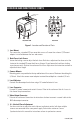
LOCATION AND FUNCTION OF PARTS 3 CAMERA MOUNT ADAPTER 5 6 LENS VIDEO 4 LEVEL OFF 10 LL ON AGC AWB ESC SYNC BLC GAM ECLP FL UP DOWN 7 DC12V THRE ECLP GRAY 24VAC GND 9 1 2 8 3 TOP/FRONT VIEW BACK VIEW Figure 1. Location and Function of Parts Lens Mount The camera has a standard CS lens mount but can use a C-mount lens when a C/CS-mount adapter is installed between the lens and camera. Back Focus Lock Screw Loosen the locking screw to adjust the back focus.
Eclipser Level Controls The eclipser function is set at the factory and usually does not need to be readjusted. However, if adjustment is necessary, refer to the section on Eclipser Adjustment in this manual. THRE Sets the level for the brightest part of the picture. Anything brighter than this adjustment will be eclipsed. ECLP Sets the brightness of the eclipsed area. GRAY Sets the brightness of the eclipsed area as viewed on a monitor.
AWB – Automatic White Balance Following are the AWB switch settings: OFF – Processes the viewed image to retain color balance in a restricted color temperature range. ON (Default setting) – Automatically processes the viewed image to retain color balance over a wide color temperature range. SYNC – Synchronization Locks the frame rate to the power supply frequency. Eliminates vertical roll caused by multiple cameras connected to the same switching device.
CONNECTIONS POWER To connect to the power supply: 1. Strip at least .50 inch (13 mm) from the power cord to expose the wires. 2. Insert the three wires into the holes in the terminal strip until they snap into place. 3. Confirm that the cord is connected to terminal securely by lightly tugging on the cord.
LENS INSTALLATION The CCC1380H-6, CCC1380H-6X, and MCC1380H-6 can use fixed, manual, or passive (DCcontrolled) auto iris lenses. The camera has a standard CS lens mount but can use a C-mount lens when a C/CS-mount adapter is installed between lens and camera. LENS MOUNTING 1. Screw the lens onto the lens mount. Be careful to prevent dust from entering the space between the lens and the CCD element. If necessary, use clean, compressed air to remove any foreign matter. 2.
BACK FOCUS ADJUSTMENT Do not release the back focus locking ring unnecessarily. Back focus adjustment has been set at the factory to the standard CS-mount back focus distance. However, once a lens is mounted it may be necessary to adjust back focal length to match the lens being used. FIXED FOCAL LENGTH LENSES 1. Mount the lens firmly to the camera. 2. With the camera operating, position the camera to view an object at least 30 feet (10 m) away. 3. Set the focus ring to infinity (∞). 4.
CAMERA SYNCHRONIZATION The power supply of each camera is set to the same synchronized phase at the factory and usually does not need to be readjusted. When using more than one camera power supply, a brief vertical roll may occur on the monitor each time a camera view is switched. To eliminate vertical roll, adjust the phase control by synchronizing, or line locking, the cameras to one another. Use the LL switches on the back of the camera to make adjustments.
ECLIPSER ADJUSTMENT The eclipser function is set at the factory and usually does not need to be readjusted. However, if fine tuning is necessary, do the following: 1. Set the DIP switches. a. AGC: OFF b. ESC: OFF c. BLC: OFF 2. Set the variable resistors and Eclipse DIP switch. a. THRE: Counterclockwise b. ECLP: Mechanical center c. GRAY: Mechanical center d. ECLP Switch: OFF 3. Set the response selector of the auto iris lens (video type) to AVERAGE.
SPECIFICATIONS GENERAL Imaging Device Picture Elements CCC1380H-6, MCC1380H-6 CCC1380H-6X Sensing Area Synchronization System PHYSICAL 1/3-inch interline transfer CCD Iris Control ENVIRONMENTAL 752H x 582V (approx. 440K) Operating Temperature 3/16 x 1/8 - inch (4.7 mm x 3.5 mm) AC line lock/DC internal 560 TV lines Electronic/passive Minimum Illumination CCC1380H-6, CCC1380H-6X 0.7 lux at F1.2, 40 IRE, AGC on, 75% reflectance MCC1380H-6 ESC 0.10 lux at F1.
PRODUCT WARRANTY AND RETURN INFORMATION WARRANTY Pelco will repair or replace, without charge, any merchandise proved defective in material or workmanship for a period of one year after the date of shipment. Exceptions to this warranty are as noted below: • Five years on the following fixed camera models: CC3701H-2, CC3701H-2X, CC3751H-2, CC3651H-2X, MC3651H-2, and CC3651H-2X.
® Worldwide Headquarters 3500 Pelco Way Clovis, California 93612 USA USA & Canada Tel: 800/289-9100 Fax: 800/289-9150 International Tel: 1-559/292-1981 Fax: 1-559/348-1120 www.pelco.