INSTALLATION/OPERATION CCC1390H Series Camera C2924M (4/05)
Contents Regulatory Notices . . . . . . . . . . . . . . . . . . . . . . . . . . . . . . . . . . . . . . . . . . . . . . . . . . . . . . . . . . . . . . . . . . . . . . . . . . . . . . . . . . . . . . . . . . . . . . . . . . . .6 Warnings . . . . . . . . . . . . . . . . . . . . . . . . . . . . . . . . . . . . . . . . . . . . . . . . . . . . . . . . . . . . . . . . . . . . . . . . . . . . . . . . . . . . . . . . . . . . . . . . . . . . . . . . . . . 6 Description . . . . . . . . . . . . . . . . . . . . . . .
Pixel Correction . . . . . . . . . . . . . . . . . . . . . . . . . . . . . . . . . . . . . . . . . . . . . . . . . . . . . . . . . . . . . . . . . . . . . . . . . . . . . . . . . . . . . . . . . . . . . . . . .35 System Information . . . . . . . . . . . . . . . . . . . . . . . . . . . . . . . . . . . . . . . . . . . . . . . . . . . . . . . . . . . . . . . . . . . . . . . . . . . . . . . . . . . . . . . . . . . . . .35 Lens Focusing . . . . . . . . . . . . . . . . . . . . . . . . . . . . . . . . . . . . . .
List of Illustrations 1 2 3 4 5 6 7 8 9 10 11 12 CCC1390H Series Camera . . . . . . . . . . . . . . . . . . . . . . . . . . . . . . . . . . . . . . . . . . . . . . . . . . . . . . . . . . . . . . . . . . . . . . . . . . . . . . . . . . . . . . . .8 DC-Drive Auto Iris Lens Connector. . . . . . . . . . . . . . . . . . . . . . . . . . . . . . . . . . . . . . . . . . . . . . . . . . . . . . . . . . . . . . . . . . . . . . . . . . . . . . . . .10 Mounting Lens to Camera . . . . . . . . . . . . . . . . . . . . .
Regulatory Notices This device complies with Part 15 of the FCC Rules. Operation is subject to the following two conditions: (1) this device may not cause harmful interference, and (2) this device must accept any interference received, including interference that may cause undesired operation. RADIO AND TELEVISION INTERFERENCE This equipment has been tested and found to comply with the limits of a Class B digital device, pursuant to Part 15 of the FCC Rules.
Description The CCC1390H Series camera is a compact, wide dynamic range (WDR), day/night camera. Its WDR technology provides up to 60 dB of dynamic range and produces superior images over a wide range of lighting conditions, including extreme backlight conditions. The camera also uses a removable infrared (IR) cut filter to switch between color and black-white (B-W) modes as environmental lighting conditions change. It also provides a dual resolution of 530 TVL (B-W) and 480 TVL (color).
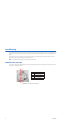
3 3a Figure 1. CCC1390H Series Camera Lens Mount: Mount a standard CS-mount lens to the CCC1390H Series camera (refer to Lens Mounting). To use a C-mount lens, install a C/CS-mount adapter. Back Focus Locking Screw: Use a 1.5-mm Allen wrench to adjust the back focus (refer to Lens Focusing). Camera Mount and 3a Mount Adapter: Use the top or bottom mount hole. The maximum thread depth (top) is 0.188 inches (4.7 mm); the adapter extends the thread depth (top) to 0.
PARTS LIST CCC1390H Series camera Quick Start Guide Safety Instructions External control connector assembly: seven-pin micro (1.25 mm) connector with wires (26 AWG) and connector cover Camera mount spacer Four-pin auto iris connector (type DN-152N) Lens mount cap Resource CD: • Installation/Operation manual: INSTALL.PDF • Quick Start Guide: QSG.PDF • Important Safety Instructions: SAFETY.PDF OPTIONAL ACCESSORIES PCMA40 Lens adapter. Adapts standard C-mount lenses to CS-mount cameras.
Lens Mounting The CCC1390H Series camera supports both manual and DC-drive auto iris lenses, either fixed focal length or varifocal. It automatically senses an auto iris lens as soon as you plug in the connector. The camera has a standard CS-mount that can accept a C-mount lens with a PCMA40 lens adapter. After mounting an auto iris lens, but before using the camera, perform the auto iris automatic adjustment procedure (refer to Auto Iris Lens Adjustment).
MOUNTING THE LENS To mount the lens onto the camera (refer to Figure 3): 1. Make sure the lens will not touch the camera imager when installed. 2. Use clean, compressed air or a clean, dry lens cloth to make sure there is no dust or other foreign matter between the lens and the camera imager. 3. C-mount lens: Screw the adapter onto the lens. 4. Screw the lens onto the lens mount. 5. DC-drive auto iris lens: Connect the four-pin connector from the lens to the connector on the back of the camera.
Camera Mounting The CCC1390H Series camera can be mounted from either the top or bottom, depending on the type of camera mount used in your installation. Use a standard 1/4-20 screw. The maximum thread depth (top) is 0.188 inches (4.7 mm). To extend the thread depth (top) to 0.25 inches (6.4 mm), use the camera mount spacer (supplied). The maximum thread depth (bottom) is 0.25 inches (6.4 mm).
Connecting Power, Video, and Control The CCC1390H Series camera offers standard power and coax video connectors as well as an external control connector. Before installation, identify how you will connect each power, video, and control lead to the camera. CONNECTING POWER The CCC1390H Series camera is designed to operate from either a 12 VDC or a 24 VAC power source. The camera automatically senses power type. Use only a Class 2 isolated power source that can supply 12 VDC ±15% or 24 VAC ±15%, 50/60 Hz.
CONNECTING AC POWER The CCC1390H Series camera requires a power supply of 24 VAC ±15% (20.4 to 27.6 VAC), 50/60Hz. Make sure the power supply has a minimum rating of 270 mA. When connecting more than one camera to the same AC transformer, remember the following: • Connect the same side of the transformer to the same terminal on all cameras. Otherwise, the cameras may be out of phase, causing a vertical roll when switching between cameras. Refer to Camera Synchronization for more information.
CONNECTING DC POWER The CCC1390H Series camera requires a power supply of 12 VDC ±15% (10.2 to 13.8 VDC). Make sure the power supply has a minimum rating of 390 mA. WARNINGS: • For safety, include a 1.0 A slow blow fuse when connecting DC power, as shown in Figure 5. • The DC power supply must be UL- and CE-certified. • Make sure you wire the power polarity correctly. To connect DC power: 1. Strip at least 0.4 inches (10 mm) of the insulation from each power wire. 2.
CONNECTING EXTERNAL CONTROL The external control connector on the rear panel lets you remotely access and control the CCC1390H Series camera. The external control connector assembly is a seven-pin micro (1.25 mm) connector with wires (26 AWG) and connector cover. You can access and configure the menu settings from any Pelco keyboard, receiver, or other device that supports the Pelco D or Pelco P protocol.
CONNECTING SERIAL CONTROL (PELCO D/PELCO P) To connect serial control to the camera (refer to Figure 7): 1. Turn off power to the camera. 2. If necessary, use a small Phillips screwdriver to remove the connector cover from the rear panel (refer to Figure 6). 3. If necessary, plug the external control connector assembly (supplied) into the camera. Then use a small Phillips screwdriver to secure the assembly connector cover to the rear panel. 4.
7. If you are not connecting additional cameras, or after adding all cameras to the chain, make sure you set the termination switch to ON for the last camera in the chain. 8. Access the CAMERA SETUP menu to set the following (refer to Camera Setup): • Set a unique ADDRESS for each camera on the serial chain. • Set the communication rate (COM SPEED) to match the rate of each camera on the serial chain.
4. Use 100-ohm twisted pair cabling to wire the device to the enclosed connector assembly. The decision to use shielded cable depends on your installation; shielded cable may be optional. EXTERNAL SWITCH PIN 1 PIN 7 INPUT (7) GND (6) Figure 8. Day/Night Filter Control Configuration 5. Wire the camera to the external switch as follows: • Pin 7 (brown, signal input) to the (+) lead on the external switch. • Pin 6 (black, ground) to the (–) lead on the external switch.
Quick Setup Several CCC1390H Series camera settings can be changed directly from the rear panel button. When a rear panel indicator is lit, the corresponding option is enabled. You can change the following options directly from the rear panel: AGC Press the button up to enable or disable automatic gain control (AGC). Refer to Automatic Gain Control (AGC) for more information. D/N Press the button left to enable or disable day and night mode. When enabled, the AUTO mode is selected.
Accessing Setup Menus NAVIGATING SETUP MENUS FROM THE REAR PANEL You can use the five-position button on the rear panel to access and navigate the setup menus (refer to Figure 10). UP SELECT RIGHT DOWN LEFT Figure 10. Rear Panel Indicators and Presses Table E lists the button presses for each menu action. Table E. Rear Panel Buttons and Actions MENU ACTION BUTTON ACTION Enter setup menus. Long center press Move up or down in menu or item options. Up or down press Move right or left in menu.
NAVIGATING SETUP MENUS FROM A PELCO CONTROLLER USING PRESET 95 TO ACCESS SETUP MENUS You can use preset 95 to access and navigate the setup menus from various Pelco controllers. Use the instructions for your controller to access the main menu. CM6700/CM6800 1. Enter the camera number and press the CAM key. 2. Enter 95 and hold the PRESET key for two seconds. A menu screen appears. 3. Move the joystick down to highlight SET. 4. Move the joystick right. The MAIN MENU appears. KBD200A/KBD300A (Direct Mode) 1.
NAVIGATING SETUP MENUS As soon as you access the MAIN MENU, the four indicators on the rear panel blink until you close the setup menu. Table F lists the buttons and actions for menu navigation. Table F. Pelco Controller Buttons and Actions MENU ACTION BUTTON ACTION Move up or down in menu or item options. Move joystick up or down. Move right or left in menu. Move joystick right or left. Select menu or item. Press the iris open button. Save setting and exit to menu. Press the iris open button.
Setup Menus The CCC1390H Series camera uses setup menus instead of hardware switches for configuring the camera. As a result, you have more options for customizing the camera for its specific application. NOTES: • After you customize any aspect of the CCC1390H Series camera, be sure to save your custom settings. (Refer to Profiles for information about saving custom settings.) • Menu items that cannot be changed are either disabled or marked with an asterisk (*).
V-PHASE ADJ LINE SYNC LINE SYNC V-PHASE ADJ > AUTO > BACK EXIT PHASE VALUE = 45 MANUAL RED/BLUE RED GAIN BLUE GAIN RED HUE BLUE HUE > -1 > -2 >1 >1 BACK EXIT SHARPNESS APERTURE GAIN > -1 BACK EXIT E-ZOOM POSITION ZOOM POSITION > OFF > BACK EXIT MASKING MASK SETTING MASK MASK EDIT MASK ERASE > OFF > BACK EXIT EDIT TITLE TITLE TITLE EDIT TITLE > OFF > BACK EXIT ABCDEFGHIJKLM NOPQRSTUVWXYZ abcdefghijklm nopqrstuvwxyz 0123456789-/ BACK BS _________________ C2924M (4/05) 25
MAIN MENU The following sections describe each menu and all settings associated with that menu. The sample screens in each section show the default settings. To display the MAIN MENU: • Press and hold the center of the button on the rear panel. Refer to Navigating Setup Menus from the Rear Panel. • Use the Pelco controller. Refer to Navigating Setup Menus from a Pelco Controller.
Table G shows the default camera settings for each profile. Figure 11 shows sample scenes for each camera profile. Table G.
EXPOSURE SETTINGS Select this option to configure the exposure settings for the CCC1390H Series camera. The default EXPOSURE SETTINGS menu appears when AUTO EXPOSURE is set to NORMAL, BLC, or WDR. When AUTO EXPOSURE is set to MANUAL, the FLICKERLESS option is replaced with the SHUTTER SPEED option.
SHUTTER SPEED Use this option to set the shutter speed manually. Select one of the following options: 1/60(NTSC), 1/50(PAL), 1/100(NTSC), 1/120(PAL), 1/250, 1/500, 1/1000, 1/2000, 1/4000, 1/10000, 1/20000, 1/50000. The default is 1/60(NTSC) or 1/50(PAL). NOTE: This option appears when AUTO EXPOSURE is set to MANUAL. AUTOMATIC GAIN CONTROL (AGC) Automatic gain control (AGC) automatically adjusts the image when the light level changes. Most scenes benefit from AGC operation. Select ON or OFF.
DAY AND NIGHT DETECTION The camera regularly checks the brightness level. When the brightness level crosses the switch threshold and lasts longer than the D&N DETECTION setting, the camera switches the filter. For example, the headlights of a passing car affect the brightness level in the camera, but not long enough for the filter to switch. The light of a cloudy day also affects the brightness level in the camera, long enough for the filter to switch. Select one of the following options: 5 SEC, 30 SEC.
FUNCTION SETTINGS Select this option to configure the function settings for the CCC1390H Series camera. FUNCTION SETTINGS LINE SYNC WHITE BALANCE MANUAL RED/BLUE GAMMA SHARPNESS E-ZOOM MASKING TITLE BACK > > AUTO > > 60%(NORM) > > > > EXIT LINE SYNCHRONIZATION Use line synchronization to eliminate the vertical roll that occurs when multiple cameras are connected to the same switching device. Line synchronization locks each camera to the same frame rate.
MANUAL RED/BLUE Select this option to display the MANUAL RED/BLUE menu. MANUAL RED/BLUE Red Gain Use this option to either increase or decrease the light level of the red elements in the camera image. Select a value between -5 and 5. The default is -1. RED GAIN BLUE GAIN RED HUE BLUE HUE > -1 > -2 >1 >1 BACK EXIT Blue Gain Use this option to either increase or decrease the light level of the blue elements in the camera image. Select a value between -5 and 5. The default is -2.
MASKING Masking lets you block out certain areas of a camera scene. Select this option to configure one to eight masks in the camera image. NOTE: When you enable masking, electronic zoom is disabled. If electronic zoom is active, masking is disabled. MASKING MASK MASK EDIT MASK ERASE > OFF > BACK EXIT Mask Use this option to enable or disable masking. The default is OFF. Mask Edit Use this option to configure one or more masks. There is no default mask. MASK SETTING To edit a mask: 1.
5. To clear a character, select BS (backspace). The camera deletes the last character entered. 6. Repeat steps 3 and 4 until you have entered the camera title. 7. When the title is correct, select BACK to return to the TITLE menu. CAMERA SETUP Select this option to configure the serial communication and rear panel function settings for the CCC1390H Series camera. Refer to Connecting External Control for information on wiring the serial interface.
PIXEL CORRECTION If white spots appear in the video image, one or more pixels on the camera imager may be defective. This condition is common to CCD camera imagers. Select this option to automatically detect and correct these defects. This feature helps you maintain image quality. PIXEL CORRECTION COVER THE LENS AND SELECT OK OK CANCEL To perform this procedure: 1. Use a lens cap to cover the lens. Make sure no light can enter the lens.
Lens Focusing After mounting the lens, you must focus your CCC1390H Series camera. You will adjust both the back focus (on the camera) and the fine focus (on the lens). NOTE: The back focus has already been adjusted using a standard CS-mount lens. However, you might need to adjust it again to match the mounted lens. 1. Auto iris only: Cover the auto iris lens with a suitable neutral density (ND) filter. This opens the iris fully. For best results, use an ND3 filter. 2.
6. Varifocal lens only: a. Set the varifocal to wide (W) and the lens focal length to far (∞). b. Adjust the back focus: (1) Use the enclosed 1.5-mm Allen wrench to loosen the back focus locking screw. (2) Turn the lens until the image is focused. (3) Tighten the back focus locking screw clockwise. WARNING: Do not over-tighten the back focus locking screw because you may damage the camera. Back focus is a coarse adjustment. You will make the fine focus adjustment in steps c and d. c.
Camera Synchronization Camera synchronization may affect installations that use two or more AC power supplies for multiple cameras. Due to different power phases, a brief vertical roll may appear on the monitor when switching between cameras. To eliminate this vertical roll, adjust the phase control to synchronize the cameras to one another.
Manual White Balance Calibration In some installations, use manual white balance to render the most accurate image color possible. Mixed color applications may affect the amount of color adjustment. For example, a small white object on a large blue surface may have a reddish tint. Manual white balance uses a calibration image to identify the correct white level. The camera then uses this white level when adjusting overall image color.
Specifications GENERAL 40 Day/Night Operation Day Night Infrared (IR) cut filter BK-7 glass, same optical displacement as day Imaging Device 1/3-inch image format Sony SS-2WD CCD Dynamic Range 60 dB maximum (WDR mode) Picture Elements NTSC PAL 768 (H) x 494 (V) (approx. 380K) 752 (H) x 582 (V) (approx. 440K) Sensing Area 3/16 x 1/8-inch (4.76 x 3.
ELECTRICAL Power Requirements CCC1390H-6 CCC1390H-6X 24 VAC ±15%/12 VDC ±15%, 60 Hz 24 VAC ±15%/12 VDC ±15%, 50 Hz Power Consumption 3.5 watts: 270 mA, 24 VAC; 390 mA, 12 VDC Power Connector 3-pin terminal strip, push-in type Video Connector BNC Auto Iris Connector 4-pin connector (miniature square) Mode Indicators 4 Controls 5-position switch Serial data termination switch Control Connector 7-pin micro (1.
PRODUCT WARRANTY AND RETURN INFORMATION WARRANTY Pelco will repair or replace, without charge, any merchandise proved defective in material or workmanship for a period of one year after the date of shipment. Exceptions to this warranty are as noted below: • Five years on FT/FR8000 Series fiber optic products. • Three years on Genex ® Series products (multiplexers, server, and keyboard).
Worldwide Headquarters 3500 Pelco Way Clovis, California 93612 USA USA & Canada Tel: 800/289-9100 Fax: 800/289-9150 International Tel: 1-559/292-1981 Fax: 1-559/348-1120 www.pelco.