I N S TA L L AT I O N M A N U A L ® PC Board Retrofit Kit for ICS100 and ICS150 ICS-KITRETRO C2405M (8/02)
INTRODUCTION Previous models of the ICS100/ICS150 back box are not compatible with the latest Camclosure™ camera module. To install the camera module, use the ICS-KITRETRO kit and modify the back box. There are two methods of installation: • The video coaxial cable is accessible and can be pulled into the back box. Refer to page 3 for installation instructions. • The video coaxial cable is not accessible and cannot be pulled into the back box. Refer to page 4 for installation instructions.
CABLE IS ACCESSIBLE Turn off power to the ICS100/ICS150. Remove the lower dome and camera module. Remove the PC board from the base of the unit. Pull the video coaxial cable into the back box. Install the new board inside the back box. Note: The block connector attached to the new PC board is not required for this installation. Either push the connector into the conduit or completely remove it. To remove the connector cut the wires attached to the board.
CABLE IS NOT ACCESSIBLE Turn off power to the ICS100/ICS150. Remove the lower dome and camera module. Remove the PC board from the base of the back box. Do not discard the screws. Reposition the board and attach it to the base using one of the screws removed in step 1.
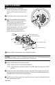
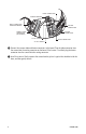
ICS100 Installation ICS150 Installation Install the new board inside the back box. Note: The BNC connector attached to the board is not required for the installation. Either push the video cable into the conduit or cut the cable and remove it. Cut the cable as close to the board as possible so that it will not interfere with the operation of the unit. Connect the input power wires to the new board. 24 VAC: Connect the wires to the two blocks labeled 24.
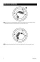
VIDEO CONNECTOR POWER TERMINAL MALE CONNECTOR FROM NEW BOARD HEATER CONNECTOR FEMALE VIDEO CONNECTOR (OLD BOARD) HEATER CONNECTOR 24 VAC JUMPER VIDEO CONNECTOR 24 VDC JUMPER Connect the camera video and heater connectors to the board. Plug the video connector from the camera into the mating connector on the board. If the heater is installed, plug the heater connector from the camera into the mating connector. Install the camera.
WARRANTY AND RETURN INFORMATION WARRANTY Pelco will repair or replace, without charge, any merchandise proved defective in material or workmanship for a period of one year after the date of shipment. Exceptions to this warranty are as noted below: • • • • • • • • • Five years on Pelco manufactured cameras (CC3500/CC3600/CC3700 and MC3500/MC3600 Series); two years on all other cameras. Three years on Genex® Series (multiplexers, server, and keyboard).
® World Headquarters 3500 Pelco Way Clovis, California 93612 USA USA & Canada Tel: 800/289-9100 Fax: 800/289-9150 International Tel: 1-559/292-1981 Fax: 1-559/348-1120 www.pelco.