ADDENDUM Addendum No.: C1588M Date: May 5, 2005 Manuals Affected: KBD300A Universal Keyboard – C527M-L KBD4000 Genex Multiplexer Keyboard - C1921M-G Manual Update: ECO 05-10910 optimizes joystick performance whenever you power up the KBD300A and KBD4000. It also provides an automatic calibration mode. Automatic Calibration of the Joystick The KBD300A and KBD4000 will calibrate the joystick automatically on power-up and every 30 minutes of inactivity.
® KBD4000 Genex® Multiplexer Keyboard Installation/ Operation Manual C1921M-G (1/04) Pelco World Headquarters • 3500 Pelco Way, Clovis, CA 93612-5699 USA • www.pelco.
2 Pelco Manual C1921M-G (1/04)
CONTENTS Section Page IMPORTANT SAFEGUARDS AND WARNINGS ........................................................................ 4 REGULATORY NOTICES ........................................................................................................... 4 DESCRIPTION ........................................................................................................................... 5 INSTALLATION ...................................................................................................
IMPORTANT SAFEGUARDS AND WARNINGS Prior to installation and use of this product, the following WARNINGS should be observed. 1. Installation and servicing should only be done by qualified service personnel and conform to all local codes. 2. Unless the unit is specifically marked as a NEMA Type 3, 3R, 3S, 4, 4X ,6 or 6P enclosure, it is designed for indoor use only and it must not be installed where exposed to rain and moisture. 3. Only use replacement parts recommended by Pelco. 4.
DESCRIPTION The KBD4000 Genex® Multiplexer Keyboard is a full-function keyboard controller for the MX4000 Genex Multiplexer and MX4000SVR Genex Multiplexer Server. This manual covers the KBD4000 keyboard’s operation with both duplex and simplex models of the multiplexer. The differences, as they pertain to the keyboard, are indicated as necessary. The mode of operation depends on whether the keyboard is connected to a multiplexer or to a server. (See Modes of Operation for an explanation.
INSTALLATION The following parts are supplied: 1 1 1 KBD4000 keyboard 25-foot (7.6 m) data cable MODES OF OPERATION The mode of operation depends on whether the keyboard is connected to a multiplexer or to a server. Multiplexer Mode A single keyboard is plugged into the back of a Genex MX4000 Multiplexer. Multiplexer Server Mode Up to four keyboards can be connected to the back of a Genex MX4000SVR Multiplexer Server. Each keyboard connected to the remote keyboard port requires a KBDKIT(-X).
UNUSED Leave switch 5 OFF. It is not used. TURBO MODE Set switch 6 ON to enable the turbo (extra fast) pan feature or OFF to disable. CAMERA ADDRESS MODE There are two modes for addressing cameras: • Set switch 7 ON if you want to address all cameras consecutively from 1-256 (refer to Table A). • Set switch 7 OFF if you want to address cameras in groups of 16 according to the multiplexer to which they are connected. For example, multiplexer 1, cameras 1-16; multiplexer 2, cameras 1-16, etc. Table A.
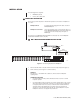
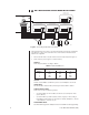
DO A MULTIPLEXER SERVER MODE INSTALLATION 1B ADDRESS #1 (LOCAL) CONTROLS MONITOR 1 ON LOCAL KEYBOARD ADDRESS #2 (REMOTE) CONTROLS MONITOR 2 ADDRESS #3 (REMOTE) CONTROLS MONITOR 3 ADDRESS #4 (REMOTE) CONTROLS MONITOR 4 1 2 3 4 5 6 7 1 2 3 4 5 6 7 ON ON R- R+ ON T+ T 1 2 3 4 5 6 7 1 2 3 4 5 6 7 TX+ TX12VAC 12VAC GND NC RX- 1 2 3 4 5 6 7 1 2 3 4 5 6 7 TX+ TX12VAC 12VAC GND NC RX- 1 2 3 4 5 6 7 TX+ TX12VAC 12VAC GND NC RX- MULTIPLEXER WALL BLOCK KBDKIT 4 5 3 6 2 7 1 8 00017 Fig
3. Replace the cover on the back of the keyboard. 4. Connect the keyboard to the MX4000SVR Multiplexer Server. You can connect up to four keyboards to the server—one to the server’s LOCAL KEYBOARD port and three to its REMOTE KEYBOARD(S) port, or all four to the remote. LOCAL KEYBOARD PORT CONNECTION Plug one end of the 25-foot (7.6 m) data cable with RJ-45 connectors supplied with the keyboard into the back of the keyboard. Plug the other end into the LOCAL KEYBOARD port on the server.
3 NOTE: If you have a multiplexer server, you must enter the Camera menu from the multiplexer’s front panel. Then you can program the cameras from the front panel of the multiplexer or from the keyboard. SETTING COAXITRON® CONTROL OF CAMERAS The KBD4000 keyboard provides Coaxitron control of pan, tilt, and lens functions. There are three Coaxitron format settings, which are set in the Camera Setup section.
PROGRAMMING NOTE: To program a multi- This section applies only to programming the multiplexer. The multiplexer can be programmed from the keyboard or from the multiplexer’s front panel. To program the multiplexer from the front panel, refer to the multiplexer manual. To program the multiplexer server, refer to the server manual. plexer if a multiplexer server is installed, you must enter programming mode from the multiplexer’s front panel.
MENUS NORMAL REC. SPEED ALARM REC.
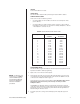
SYSTEM SETUP (VIEW KEY) 2/6/8 Hr 2/6/8 Hr MAIN MONITOR VIDEO MAIN MONITOR DISPLAY HIGH RESOLUTION *2,6,or 8 Hr 12 Hr 16 Hr 18 Hr 24 Hr 48 Hr 72 Hr 84 Hr 96 Hr 120 Hr 168 Hr 180 Hr 240 Hr 360 Hr 480 Hr 600 Hr 720 Hr 960 Hr ** ** RESET ACTIVITY DETECTION ALL CH TO HIGH RESOLUTION REDUCED FLICKER * 2/6/8 HR FOR NTSC/EIA MODEL MULTIPLEXERS, 3 HR FOR PAL/CCIR MODELS. REMAINING RECORD SPEEDS DEPEND UPON VCR MODEL. ** NOT SHOWN ON DUPLEX MONOCHROME MODELS OR SIMPLEX MULTIPLEXERS Figure 5.
Record Speeds Sets the speed at which the VCR normally records video and at which it records when there is an alarm(s). Setting the speeds in the System Setup menu also sets the speeds in the Record Setup and Custom VCR Setup menus. Main Monitor Video (Duplex Color Models Only) COMPOSITE is standard video on coaxial cable. SVHS is higher resolution video on a special cable. Main Monitor Display The options are HIGH RESOLUTION and REDUCED FLICKER.
ADVANCED SYSTEM SETUP (VIEW KEY) DATE FORMAT MM-DD-YY PASSWORD DISABLED FRONT PANEL CONTROL ENABLED MAIN MONITOR DISPLAY RESPONDS TO NONE SPOT MONITOR DISPLAY SEQUENCE RESPONDS TO ALARMS *** AUX MONITOR DISPLAY *** RESPONDS TO SEQUENCE BLANK TRACK MAIN BLANK ACTIVITY CAMERA TYPES ALL COLOR UNIT ID COMM. TYPE 001 MASTER (KBD-T/D) RELAY OUTPUT ALARM BLANK CAM 1 CAM 16 SEQUENCE ALL COLOR* COLOR & B/W RESERVED 001–240 MASTER (KBD-T/D)** (1) SLAVE (2) * ALL B/W SHOWN ON MONOCHROME MODELS.
Spot Monitor Display • Select BLANK, SEQUENCE, or TRACK MAIN if you want the spot monitor to switch to cameras that have alarms or activity detection. Then under RESPONDS TO, select ALARMS, ACTIVITY, or ALARMS/ACTIVITY. • Select NONE if you are using the spot for normal video and you do not want alarms or activity detection to override what you are watching. The options are defined as follows: • BLANK – Lets you view an individual camera, but you cannot run a sequence.
Comm. Type • In polled communication mode (switch 4 off), one multiplexer (any one) must be the master. Only one multiplexer can be master; all others must be slaves. The master multiplexer communicates with the slave multiplexers. • In non-polled communication mode (switch 4 on), all multiplexers must be slaves (the keyboard is master). The default is MASTER for duplex models and MASTER (KBD T/D) for simplex models. Relay Output This operates the relay on the back of the multiplexer.
RECORD SETUP (LIVE/VCR KEY) NORMAL REC. SPEED ALARM REC.
VCR Switch Pulse • ENABLED + means the multiplexer waits for a positive head switching pulse from the VCR. If the multiplexer does not get a pulse from the VCR (because of a broken wire or the VCR does not give a pulse in some modes), it may appear the multiplexer is not working properly. • ENABLED – (minus sign) means the multiplexer waits for a negative head switching pulse from the VCR. • DISABLED means the VCR head switching pulse is not used.
CUSTOM VCR SETUP (LIVE/VCR KEY) *2,6,or 8 Hr 12 Hr 16 Hr 18 Hr 24 Hr 48 Hr 72 Hr 84 Hr 96 Hr NORMAL RECORD SETUP RECORD SPEED 2/6/8 Hr SWITCH INTERVAL 003 ALARM RECORD SETUP RECORD SPEED 2/6/8 Hr SWITCH INTERVAL 003 120 Hr 168 Hr 180 Hr 240 Hr 360 Hr 480 Hr 600 Hr 720 Hr 960 Hr 003 TO 509 ** EXIT BACK * 2/6/8 HR FOR NTSC/EIA MODEL MULTIPLEXERS, 3 HR FOR PAL/CCIR MODELS. REMAINING RECORD SPEEDS DEPEND UPON VCR MODEL. ** VCR TYPE IN RECORD SETUP MENU MUST BE SET TO CUSTOM IN ORDER TO MAKE SELECTIONS.
CAMERA SETUP (NUMBER AND CAM KEYS) NORMAL COVERT CAMERA 1 NORMAL * ä à á â c ê ë è ï î ì ‹ › , (COMMA) VIDEO INPUT TERMINATION 75 OHM ALARM INPUT NORMALLY OPEN COAXITRON FORMAT EXTENDED ACTIVITY DETECTION SET DETECTION MASK ENABLED ENABLED DISABLED EXTENDED OFF STANDARD OPEN CLOSED * ONLY NINE CHARACTERS APPEAR WHEN IN THE 16-CAMERA DISPLAY. Figure 9. Basic Camera Menu To program a camera input: 1. Press the MAIN MONITOR key. 2. Select the camera. Addressing by Multiplexer (Switch 7 OFF) a.
(If you play back the tape on the same equipment, any covert picture will still appear blanked. Change the setting to NORMAL to see the picture.) Video Termination • Set to 75 OHM when equipment is connected to the video IN connector only. • Set to LOOP HI-Z when equipment is also connected to the video OUT (looping) connector. Equipment connected to the looping connector must be terminated at 75 ohms.
ACTIVITY DETECTION MASK SETUP ACTIVITY DETECTION MED SENSITIVITY SET ALL CLEAR ALL EXIT LOW SENSITIVITY MED SENSITIVITY HIGH SENSITIVITY TEST ACTIVITY BOX SET ACTIVITY BOX CLEAR Figure 10. Activity Detection Mask Activity detection continually monitors selected camera inputs for motion. When motion is detected, the multiplexer shows and records that camera(s) more frequently. Activity detection is most effective when only a few cameras are showing activity.
7. Turn activity boxes on or off (the default is all are on). • To turn on all boxes, use the joystick to choose SET ALL. Press the OPEN key. All boxes contain a symbol (as shown in Figure 10). The multiplexer monitors activity in those boxes. • To turn off all boxes, use the joystick to choose CLEAR ALL. Press the OPEN key. All boxes are blank. • To turn on or off an individual box, use the joystick to select the box. Press the OPEN key to toggle the box on or off.
3. Press the SEQ key for about three seconds. 4. Type the password (3916), if requested. Enter it by pressing each number key followed each time by the CAM key. The Sequence menu appears. The currently selected menu item blinks. 5. Use the joystick to move among items on the screen. When the menu item you desire is highlighted (blinking), press the OPEN key to cycle through the options to select the one you want. 6. Press the OPEN key to exit programming mode.
MULTIPLE CAMERA DISPLAY SETUP You can use the keyboard to configure multiple camera display formats. The LEDs above the camera buttons on the multiplexer light to indicate which cameras are being displayed. PROGRAMMING THE PICTURE-IN-PICTURE DISPLAY ( ) You can program the on-screen location and size of the picture-in-picture (PIP) display. PIP is unavailable in duplex VCR playback and in simplex record mode. To program the PIP display: 1. Press the MAIN MONITOR key. 2.
PROGRAMMING THE 9-CAMERA DISPLAY ( ) You can program two groups of nine cameras each. Both groups can be programmed to include any nine cameras. is unavailable in simplex record mode. To program the nine-camera displays: 1. Press the MAIN MONITOR key. 2. Use the number pad to enter the multiplexer’s address (1-16 if the keyboard is connected to a multiplexer; 1-8 if the keyboard is connected to a server), and then press the UNIT key. 3. Press the to call up a nine-camera display.
PROGRAMMING MENU DEFAULTS Table D.
PROGRAMMING A PRESET NOTE: DIP switch number 8 must be ON for programming. 1. Press the MAIN or SPOT MONITOR key. The green LED over the MAIN or SPOT key lights. When using the MAIN MONITOR, the SPOT MONITOR DISPLAY menu item in the Advanced System Setup menu must be set to TRACK MAIN (refer to the Advanced System Setup section). NOTE: The LEDs above 2. the camera buttons on the multiplexer light to show which cameras are being displayed. Select the camera. Addressing by Multiplexer (Switch 7 OFF) a.
OPERATION 2 3 5 4 6 7 1 8 LIVE/VCR * The turbo pan feature * The turbo pan feature be disabled. Place maymay be disabled. switch Place switch66on onthe the rear DIP switch switch block rear panel panel DIP See blockininthe theoff offposition. posi1. 1. tion.Figure See Figure MONITOR 19 UNIT MAIN SPOT 1 2 3 4 5 6 7 8 9 CAM 0 CLEAR SEQ VIEW PATTERN PRESET NEAR FAR OPEN CLOSE ON OFF 18 9 17 10 KBD4000 MADE IN USA.
Table E. Operation Guide Refer to “Functions” in the Index for an alphabetical list of the operations described in Table E. NOTE: References to switch 7 in this table refer to the switch behind the panel on the back of the keyboard.
Table E. Operation Guide (Continued) OPERATION Exit main tracking. Call a group of cameras to the main monitor. Display a picture-inpicture (PIP) insert on the main monitor. KEYBOARD COMMAND 1. Go to the Advanced System Setup menu. 2. Move the joystick so the cursor highlights SPOT MONITOR DISPLAY items. 3. Press the OPEN key until SEQUENCE or BLANK is displayed. 4. Exit the Advanced System Setup menu. 1. Press the MAIN MONITOR key. The green LED over the MAIN key lights. 2.
Table E. Operation Guide (Continued) OPERATION Zoom on a camera on the main monitor. KEYBOARD COMMAND 1. Press the MAIN MONITOR key. The green LED over the MAIN key lights. 2. Select the camera. Addressing by Multiplexer (Switch 7 OFF) a. On the number pad, press the multiplexer’s address number (1-16 if the keyboard is connected to the multiplexer; 1-8 if connected to a server), and then press the UNIT key. The LED displays the address. b.
Table E. Operation Guide (Continued) OPERATION Run a sequence of cameras from one multiplexer on the spot monitor. (SPOT MONITOR DISPLAY in the Advanced System Setup menu must be in SEQUENCE.) KEYBOARD COMMAND 1. Press the SPOT MONITOR key. The green LED over the SPOT key lights. 2. Select a camera on the multiplexer you want to sequence. RESULT Starts the sequence of individual cameras on the spot monitor. Addressing by Multiplexer (Switch 7 OFF) a.
Table E. Operation Guide (Continued) OPERATION KEYBOARD COMMAND RESULT 1. Follow the steps under “Run a sequence of cameras from one multiplexer on the main monitor” or “Run a sequence of cameras from one multiplexer on the spot monitor” to start sequencing the cameras on the main and spot monitors of individual multiplexers you want to sequence. 2. Hold down the SEQ key for about three seconds to start sequencing the multiplexers. Sequence the picture-in-picture (PIP) display. 1. Press the 2.
Table E. Operation Guide (Continued) OPERATION Start auto scan with 15-bit receiver. KEYBOARD COMMAND 1. Press the SPOT MONITOR key. The green LED over the SPOT key lights. 2. Select the camera. RESULT Starts auto scanning. Addressing by Multiplexer (Switch 7 OFF) a. On the number pad, press the multiplexer’s address number (1-16 if the keyboard is connected to the multiplexer; 1-8 if connected to a server), and then press the UNIT key. The LED displays the address. b.
Table E. Operation Guide (Continued) OPERATION Turn an auxiliary function on or off. KEYBOARD COMMAND 1. Press the SPOT MONITOR key. The green LED over the SPOT key lights. 2. Select the camera. RESULT The auxiliary function operates. Addressing by Multiplexer (Switch 7 OFF) a. On the number pad, press the multiplexer’s address number (1-16 if the keyboard is connected to the multiplexer; 1-8 if connected to a server), and then press the UNIT key. The LED displays the address. b.
TROUBLESHOOTING If you have difficulty operating your system, run through the following checklist to see if you can solve the problem. 1. Are the keyboard switches set properly? 2. Is the equipment wired properly? 3. Are the menu options in the multiplexer(s) and server set properly? 4. Is the multiplexer set to the correct mode for live video or tape playback? 5. Only the main monitor displays multiple-screen images. The spot monitor displays fullscreen views only. 6.
16. If you have a server, each keyboard controls its corresponding monitors. • In SINGLE mode, keyboard 1 controls monitor 1, keyboard 2 controls monitor 2, etc. • In PAIRED mode, keyboard 1 controls monitor 1 (main) and monitor 2 (spot), and keyboard 3 controls monitor 3 (main) and monitor 4 (spot). In paired mode, keyboards 2 and 4 are not used. 17.
INDEX sequence pip display 35 set main tracking 31 start a pattern 36 start auto scan (15-bit) 36 start manual scan (15-bit) 36 start random scan (15-bit) 36 stop auto or random scan 36 stop sequence of multiplexers 35 turn auxiliary function on/off 37 zoom camera on main monitor 33 A Activity detection 14 Activity detection mask setup 23 Address setting 9 Address switch setting 6, 8 Addressing by multiplexer 21, 23, 29 Addressing consecutively 21, 23, 29 Advanced system setup menu 15 Alarm handling 19 Ala
O S Operating differences 5 Operating modes 5, 6 SEQ key 24 Sequence setup 24 Set up multiple camera display 26 Sixteen-camera display programming 27 Slave/master 11 Slave/master designation 9 Spanish 11 Specifications 39 Spot monitor display 16 Switch settings 6 System setup menu 13 P Paired mode 9 Password 11, 15 Pattern programming 29 Playback format 19 Polled/non-polled communication 9 Polled/non-polled communication mode 11, 17 Preset programming 29 Program mode switch setting 7 Programming a patte
WARRANTY AND RETURN INFORMATION WARRANTY Pelco will repair or replace, without charge, any merchandise proved defective in material or workmanship for a period of one year after the date of shipment. Exceptions to this warranty are as noted below: • • • • • • • • • Five years on Pelco manufactured cameras (CC3500/CC3600/CC3700 and MC3500/MC3600 Series); two years on all other cameras. Three years on Genex® Series (multiplexers, server, and keyboard).