® DX1000 Series Digital Video Recorder Installation/ Operation Manual C680M-G (7/01) Pelco • 3500 Pelco Way • Clovis, CA 93612-5699 USA • www.pelco.
CONTENTS Section Page IMPORTANT SAFEGUARDS AND WARNINGS ................................................................ 3 DESCRIPTION ................................................................................................................... 3 MODELS .................................................................................................................... 3 FRONT PANEL CONTROLS ..............................................................................................
IMPORTANT SAFEGUARDS AND WARNINGS Prior to installation and use of this product, the following WARNINGS should be observed. 1. Installation and servicing should only be done by qualified service personnel and conform to all local codes. 2. Unless the unit is specifically marked as a NEMA Type 3, 3R, 3S, 4, 4X ,6 or 6P enclosure, it is designed for indoor use only and it must not be installed where exposed to rain and moisture. 3.
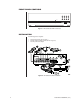
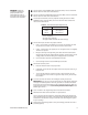
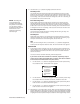
FRONT PANEL CONTROLS Power Record 1 2 3 4 5 6 7 8 9 0 Stop Function Search Play/Pause Search Figure 1. DX1000 Series DVR Front Panel INSTALLATION The following parts are supplied: 1 1 1 DX1000 Series DVR (refer to Figure 1) Induced Voltage Protector (refer to item 4c in Figure 2) 230 VAC power cord adapter Figure 2.
WARNING: Adequate ventilation is required for proper operation of the DVR. Allow two inches of space above the unit and on each side for air circulation. 1 Connect cameras to the CAMERA INPUT connectors (BNC) on the rear of the DVR. Refer to Table A for video coaxial cable distances. 2 Connect a monitor to the MONITOR OUTPUT connector (BNC) on the rear of the DVR. Refer to Table A for video coaxial cable distances.
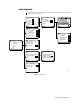
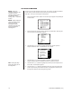
PROGRAMMING Programming allows you to configure camera and alarm operation, set the system date and time, and define a password. CAMERA CAMERA 1* Camera 1: On Camera 2: On Camera 3: On Camera 4: On Preview: On fps (Frame Per Second): 01 Quit Camera operation: On Automatic Recording: On Automatic recording time change Resolution Quit * Same menu for cameras 2-4.
CAMERA MENU Use this menu to define the following: • • • • • • Which cameras the DVR will record Whether starting and stopping of recording will be done manually or automatically What the record rate (frames per second) will be What the recording resolution (low to high) will be Whether live video can be viewed in record mode Starting and stopping times for scheduled recording Skip steps 1 and 2 if you are already in the Setup Menu. 1. Press and hold the Function button. The Function Key List appears.
5. The fps (Frame Per Second) field shows the recording rate for all cameras. To change the fps, use the Search (<>) buttons to highlight fps, and then use the number keypad to enter the frames per second. The maximum frames per second is determined by the number of cameras being recorded and whether the Preview feature is on or off. Refer to Table B for the maximum frames per second. Refer to Table C in the Operation section for recording times. Table B. Maximum Frames per Second 6.
10. Use the Search (<>) buttons to highlight each field in the menu. Recording Times The recorder will record continuously between the specified times. Use the number buttons to enter the hour of the starting time and ending time. Enter two digits. Enter the hours in 24-hour format. For example, enter 08 for 8 a.m. and 15 for 3 p.m. For 24hour recording, enter a start time of 00 and an ending time of 24. For no recording, enter a start time of 24 and an end time of 00.
ALL RESOLUTION MENU NOTE: Setting the resolution in this menu will overwrite all camera resolution settings made in the individual camera settings (step 11 of previous section). Use this menu to set the resolution for all cameras. If you want to use different resolutions for the cameras, set the resolutions in the Camera menu (previous section). Skip steps 1 and 2 if you are already in the Setup Menu. 1. Press and hold the Function button. The Function Key List appears. Keep holding the Function button.
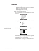
ALARM OUTPUT MENU The ALARM output on the rear panel is a single-pole, normally open, latching, dry contact. This output can be used to notify you if there has been an alarm event that might require review. The alarm output can be enabled or disabled (armed/disarmed) manually, or it can be programmed to enable (arm) or disable (disarm) at the same time automatically every day. NOTE: The alarm output programming does not affect recording. It only affects the operation of the alarm output relay.
3. Use the Search (<>) buttons to move around within the menu. Highlight Alarm Output and press the Play/Pause button to select. The Alarm Output menu appears. ALARM OUTPUT Enable Alarm Output: 00 Disable Alarm Output: 24 Automatically Enable Alarm Output: On Quit 00425 4. Use the Search (<>) buttons to highlight the fields for starting and ending times. When you highlight a field, use the number buttons to enter the time. The starting and ending times refer to the hour. Enter two digits.
TIME MENU The DVR uses the time and date to index video on the hard disk drive so you can find it later. Changing the time can cause the DVR to work improperly when you try to play back video. If you set the hour ahead, this is not a problem. But if you set the hour back, there will be more than one recording at the same time. Therefore, you should refrain from making frequent changes as this will complicate searching by time and date.
PASSWORD MENU Use this menu to change the password (optional). Skip steps 1 and 2 if you are already in the Setup Menu. 1. Press and hold the Function button. The Function Key List appears. Keep holding the Function button. FUNCTION KEY LIST 0 : Setup 1 : Camera 1 recording/stop 2 : Camera 2 recording/stop 3 : Camera 3 recording/stop 4 : Camera 4 recording/stop 5 : All the cameras recording 6 : All the cameras stop : Alarm On : Alarm Off 2.
HELP If the Help function is enabled, the Help screens appear on the monitor whenever power is turned on. Skip steps 1 and 2 if you are already in the Setup Menu. 1. Press and hold the Function button. The Function Key List appears. Keep holding the Function button. FUNCTION KEY LIST 0 : Setup 1 : Camera 1 recording/stop 2 : Camera 2 recording/stop 3 : Camera 3 recording/stop 4 : Camera 4 recording/stop 5 : All the cameras recording 6 : All the cameras stop : Alarm On : Alarm Off 2.
OPERATION The Record LED on the front panel indicates what the DVR is doing. Recording: Playback: Fast Playback: Alarm Event Recording Enabled: Stop: Red (blinking) Green (steady) Green (blinking) Yellow (steady) Off VIEWING CAMERAS If the Preview feature in the Camera menu is On, you can view live video on the monitor. Video is displayed full-screen only if one camera is turned on. If more than one camera is turned on, video is shown in a quad view.
RECORDING EXAMPLE A company has a rear door that is not to be opened for any reason between 5 p.m. and 7 a.m. During the day, the area around this door is recorded continuously (scheduled recording), but to conserve disk space, the area is only recorded at night if the door is opened (event recording). In this case, the recorder would be programmed for scheduled (continuous) recording from 7 a.m. to 5 p.m. and event recording from 5 p.m. to 7 a.m. (refer to Camera Menu in the Programming section).
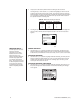
PLAYBACK START PLAYBACK To begin playback: 1. Press the Play/Pause button. 2. Enter the password if requested. 3. The Play window appears. PLAY From to 2000 / 01 / 01 2000 / 03 / 03 Data search is possible by Year/month/date. Camera 3CH * Input camera channel number. Playing time 2000 / 02 / 05 / 09 / 00 PLAY SCREEN 4. Press a number button (1-4) to select the camera to view. The camera channel appears on the screen. 5. Press the Search (>>) button to go to the time and date fields.
STOP PLAYBACK To stop playback: Press the Stop button. Playback stops and recording resumes if the DVR is programmed for automatic recording. Live video appears on the monitor if the Preview feature is turned on. PLAYBACK FOLLOWING TIME CHANGES The DVR uses the time and date to index video on the hard disk drive so you can find it later. Changing the time can cause the DVR to work improperly when you try to play back video. If you set the hour ahead, this is not a problem.
ALARM OPERATI0N When an alarm input on the rear of the DVR is triggered, two things can happen: • The DVR will start recording. • The alarm output relay will turn on a light or other device to alert you that there has been an alarm. Application example: A company has a rear door that is not to be opened for any reason between 5 p.m. and 7 a.m. During the day, the area around this door is recorded continuously, but the area is only recorded at night if the door is opened.
Relay Operation When an alarm input is activated, a 20-second countdown begins before the relay turns on the warning light or buzzer. The numbers appear on the screen. This is an entry feature that allows you to disarm the alarm when you enter your own premises. Once the relay operates, the light or buzzer remains on until you manually turn off the relay. Turning Off the Relay 1. Press and hold the Function button. The Function Key List appears. Keep holding the Function button.
TROUBLESHOOTING Symptom: You cannot stop recording even after pushing the Stop button. Check the Camera menu for the camera(s) that will not stop recording. Make sure the Automatic Recording feature is turned off. Symptom: There is no video on the monitor while the DVR is recording or is in recording standby mode (not recording). Check the Camera menu for the camera(s). Make sure Preview is turned on.
REGULATORY NOTICES This equipment has been tested and found to comply with the limits of a Class B digital device, pursuant to part 15 of the FCC rules. These limits are designed to provide reasonable protection against harmful interference in a residential installation. This equipment generates, uses, and can radiate radio frequency energy and, if not installed and used in accordance with the instructions, may cause harmful interference to radio communications.
PRODUCT WARRANTY AND RETURN INFORMATION WARRANTY Pelco will repair or replace, without charge, any merchandise proved defective in material or workmanship for a period of one year after the date of shipment. Exceptions to this warranty are as noted below: • Five years on FT/FR8000 Series fiber optic products. • Three years on Genex ® Series products (multiplexers, server, and keyboard).