O P E R AT I O N / P R O G R A M M I N G ® DX7000 Series Digital Video Recorder C665M-C (5/03)
CONTENTS Section Page GETTING STARTED ............................................................................................................................................................................................................. 5 DISPLAY MODE .................................................................................................................................................................................................................. 6 SYSTEM SETUP .........................
PRESETS ................................................................................................................................................................................................................... 44 HOW TO MOVE TO A PRESET ......................................................................................................................................................................... 44 PRESET TOURS ...............................................................................
C665M-C (5/03)
GETTING STARTED You will need to install your unit before using this manual. Refer to the installation manual supplied with the DX7000 for installation instructions. Once the system is installed open the front panel of the DVR and press and hold the power switch down until the LED turns green. The operating software of the DX7000 will check the hardware configuration of the system. After a few seconds the Add New Hardware Wizard pops-up on the screen.
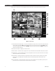
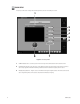
DISPLAY MODE Display mode is the main screen of the DX7000 Series DVR. Use this screen to access Search, Setup, and PTZ modes. 1 2 3 4 5 6 7 8 9 13 12 11 10 Figure 1. Display Mode 1 Camera Name and Recording Status – The colored circle located to the right of the on-screen camera name indicates the recording status of the camera. RED indicates that the camera is recording continuously. If the circle is BLUE, camera recording was triggered by motion detection.
COPY Button (Backup) – Click the COPY button to record to a backup device that is recommended by Pelco. NOTE: The copy button appears only if a backup device, such as Pelco’s DX7000CD and software, are installed. Refer to the How to Copy to a Backup Device section of this manual for more information. 8 EXIT Button – Click the EXIT button to exit the DX7000 program and shutdown the system.
SYSTEM SETUP To set up the DX7000 Digital Video Recorder, click the SETUP button located in the DISPLAY mode. The SETUP mode appears on the screen. To exit the SETUP mode and return to the DISPLAY mode click the EXIT button. WARNING: The DX7000 server will stop recording and all remote site users will be disconnected during system setup.
CAMERA SETUP Use this screen to enable or disable camera inputs, input camera name, and set signal type (NTSC/PAL). All cameras are enabled the first time the DX7000 DVR is started. Disable any camera input that is not being used. Disabled cameras can increase record rate. 1 2 3 4 Figure 2. Camera Setup Menu 1 CAMERA NAME Box – To name a camera drag the cursor over the text in the CAMERA NAME box and type in the new name. Up to 70 characters can be entered in the box.
COLOR SETUP If required, use this screen to adjust the contrast, brightness, and color level settings of a scene. 1 2 3 4 5 6 8 7 Figure 3. Color Setup Menu 10 1 CAMERA Selection Box – Use the drop down menu to the right of the camera selection box to select a camera. 2 CON (Contrast) Slider Bar – Drag the cursor on the CON bar to change the contrast value of the viewed and recorded scene. Proper adjustment will allow maximum gradations between the darkest and lightest parts of a scene.
4 RED Slider Bar – Drag the cursor on the RED bar to adjust the red color level of the viewed and recorded scene. 5 GREEN Slider Bar – Drag the cursor on the GREEN bar to adjust the green color level of the viewed and recorded scene. 6 BLUE Slider Bar – Drag the cursor on the BLUE bar to adjust the blue color level of the viewed and recorded scene. 7 DEFAULT COLOR Button – Click the Default Color button to return all color settings to their default settings.
SCHEDULE SETUP The default recording schedule for the DX7000 is to continuously record all enabled cameras twenty-four hours a day, seven days a week. Pelco recommends clearing the default setting before programming a schedule. To clear the default setting click the CLEAR ALL SCHEDULE button.
2 START TIME – Program the time to start recording. If you want GROUP 1 to start recording at 6:30 in the morning, use the arrow keys and set the START TIME to 3 END TIME - Program the time to stop recording. If you want GROUP 1 to stop recording at 5:30 in the evening, use the arrow keys and set the END TIME to 4 CLEAR ALL SCHEDULE – Clears all group schedules. FULL RECORD – Configures Group 1 to record continuously all enabled cameras twenty-four hours, seven days a week.
HOW TO SET A SCHEDULE Example: Record 4 cameras with motion detection from Monday to Friday, 8:00 AM - 6:00 PM; Saturday 8:00 AM - 2:00 PM; and no recording on Sunday. Step 1 – Select GROUP 01 and set the START TIME to 8:00 and END TIME to 18:00. Step 3 – Select 01, 02, 03, and 04 in CAMERA section. Step 2 – Check MON, TUE, WED, THU, and FRI in the DAY OF WEEK section. Step 4 – Select 01, 02, 03, and 04 in MOTION section.
Step 5 – Select GROUP 02 and set the START TIME to 8:00 and END TIME to 14:00. Step 7 – Select 01, 02, 03, and 04 in CAMERA section. Step 6 – Check SAT in the DAY OF WEEK section. Step 8 – Select 01, 02, 03, and 04 in MOTION section.
SPEED SETUP Use the Speed Setup window to program the recording rate for each camera and to program the pre-alarm function for motion and sensor recording modes. The total images per second available to be distributed for all enabled cameras varies by the mode selected. In duplex mode the maximum recording speed is 60 fps. In simplex mode the maximum recording speed is 160 fps. In backup mode, the maximum fps is 40. (See item 9 and description for further details.
4 IMAGE QUALITY Slider Bar – Sets the quality of the recorded image. Image quality affects storage capacity and transmission rate. More bandwidth and storage capacity is required for high quality images. VHS image quality is equal to 43%. 5 MOTION EXT. (Extended) DURATION Slider Bar – Sets recording time after motion is detected. 6 SENSOR EXT. (Extended) DURATION Slider Bar – Sets recording time after a sensor is triggered.
MOTION SPEED MENU 1 2 3 Figure 6. Motion Speed Menu 18 1 MOTION Button– Select the MOTION button to open the motion speed menu. Use this menu to set motion detection and pre-alarm recording speeds. 2 Motion Recording Speed Slider Bar –Use the slider bar to set the recording rate for motion detection. If the camera is already set to record continuously, the recording rate for motion can be set to record at a higher speed.
SENSOR SPEED MENU 1 2 3 Figure 7. Sensor Speed Menu C665M-C (5/03) 1 SENSOR Button – Select the SENSOR button to open sensor speed menu. Use this menu to set the sensor detection and pre-alarm recording speeds. 2 Sensor Recording Speed Slider Bar - Use the slider bar to set the recording rate for sensor detection. If the camera is already set to record continuously, the sensor recording rate can be set to record at a higher speed.
MOTION DETECTION SETUP Motion detection recording saves hard drive space and makes it easier to search and retrieve recorded data. Use the motion detection menu to select the motion detection areas of a scene. See item 5 for details and limitations. 1 2 3 4 5 Figure 8. Motion Detection Setup Menu 20 1 CAMERA Selection Box – Displays the name of the camera selected for motion detection setup.
4 CLEAR ALL BLOCK Button – Deletes all motion detection area blocks for the selected camera. 5 Camera View - A red box indicates an area is set for motion detection. A maximum of 10 detection areas can be set per camera. HOW TO SET UP MOTION DETECTION AREAS a. Select a camera: 1. Click the pull down arrow to the right of the CAMERA window. 2. Select a camera. 3. The selected camera appears in the CAMERA window. b. Select detection areas: 1.
PASSWORD SETUP DX7000 features four levels of password protection to prevent unauthorized changes or use of the system. The following are the four password levels: Administrator Full rights, able to access and setup all system features. Search User Has permission to view live video and search recorded video. The user does not have permission to access any other system features. PTZ/Backup User Has permission to view live video, use pan, tilt, and zoom controls, and archive files to a backup device.
3 Number Buttons – Use number buttons to input password. 4 ENTER Button – Select to apply password to level. 5 CLEAR Button – Clears password input area. To set a password: a. Use the left mouse button to select the password level. b. Click the number buttons to input a password. c. Click ENTER to save the password. To clear a password: a. Use the left mouse button to select the password level. b. Click CLEAR. c. Click ENTER.
PAN AND TILT SETUP Set the pan and tilt protocol for the DX7000 by scrolling through the selections in the RX TYPE box. Figure 10. Pan and Tilt Protocol Menu Do the following to set PTZ protocol: a. Click the arrow to the right of the RX TYPE box. b. Scroll through the available selections. c. Click a selection.
QUIT TO EXPLORER The DX7000 uses a Windows-based operating system. To set a network address, add hardware, or change clock settings, click the Quit To Explorer button. IMPORTANT: Consult your network administrator to avoid possible network conflicts and to obtain the information required to setup a network address. UPDATE PROGRAM To update system software: a. Click the Update Program button. b. Select the drive and folder with the update software. c.
HOW TO OPERATE PTZ To control pan, tilt, and zoom functions and to set patterns, preset tours, and presets, click the PTZ button located in the DISPLAY mode. The PTZ mode appears on the screen. To exit the PTZ mode and return to the DISPLAY mode, click EXIT. FOR FUTURE USE PRESET BUTTONS CAMERA 01193 Figure 11.
PTZ CONTROLS To operate pan/tilt/zoom functions on controllable systems, do the following: a. Select a camera. • Move the cursor to a camera screen view. Double-click the left mouse button. • A single camera view appears on the screen and the camera number (1 through 16) appears in the center of the pan and tilt control (refer to Figure 12). b. Use the left and right arrow buttons to pan left and right. c. Use the up and down arrow buttons to tilt up and down. d.
PATTERNS A pattern is a user-defined, viewable camera path with a definite beginning and end. The pattern can consist of any standard pan and tilt or lens commands. Once defined the pattern is easily activated with the press of an on-screen menu button. The pattern will run continuously until it is deactivated with another press of the menu button. HOW TO PROGRAM A PATTERN a. b. c. d. e. Click the PTZ button in the DISPLAY Mode. The PTZ Mode appears. Select a camera.
PRESET TOURS A preset tour is a programmed sequential execution of preset positions. HOW TO PROGRAM A PRESET TOUR a. b. c. d. e. f. g. Click the PTZ button in the DISPLAY Mode. The PTZ Mode appears. Click PRESET. Select a camera by moving the cursor to the desired camera view and clicking the left mouse button. Click the TOUR button to turn it ON. Click the SET button to turn it ON. Click preset buttons in any sequential order to program a tour.
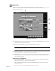
SEARCH To search recorded data on the hard disk drive or secondary device, click the SEARCH button located in the DISPLAY mode. The SEARCH mode appears on the screen. To exit the SEARCH mode and return to the DISPLAY mode, click EXIT. 1 2 3 4 5 14 12 11 10 9 8 7 6 13 Figure 13. Search Mode 1 Year and Month to Search – Displays year and month to search. 2 Day Search – Days with recordings are highlighted with a yellow circle. The day selected is highlighted with a green circle.
5 Playback Buttons – Use to search saved data. PLAYBACK PREVIOUS IMAGE NEXT IMAGE STOP GO TO LAST IMAGE RECORDED ON HDD GO TO THE FIRST IMAGE RECORDED ON HDD FAST PLAYBACK 00953 6 Eject Button – Ejects CD-RW. 7 Primary/Secondary Device Button – Search button for backup (secondary) storage device. It appears only if CD-RW software and CD-RW drive are installed. 8 AVI Button – Creates and saves an AVI file to a backup storage device.
DATE/TIME SEARCH a Press the Camera button. b Use the arrow buttons to select the year and date to search. c Select the day to search. Days with recordings are highlighted with a yellow circle. The selected day is highlighted with a green circle. d Use the arrow buttons to select the hour and minute to search. e Use the playback buttons to review a recording. b c d e a Figure 14. Date/Time Search SLIDER SEARCH a Press the Slider button.
INDEX SEARCH a Click the INDEX SEARCH button. b The Index Data List appears. Select the event type (motion or sensor) to search. Enter the START TIME and END TIME of search. Click the Camera button. Select a camera to view. Depending on the amount of data it may take several minutes before an Index List is displayed. Double-click on one of the data files to display the recording. b a Figure 16.
HOW TO COPY TO A BACKUP DEVICE To backup data to an external device, click the COPY button located in the DISPLAY mode. NOTE: The COPY button appears only if a backup device is installed and BACKUP mode, located in the SPEED SETUP menu, is selected. INITIATE DX7000 COPY BUTTON IMPORTANT: The copy button will not appear in the Display mode if the following procedures are not completed. a. b. c. 34 Install the backup device and software.
BACKUP WINDOW 1 2 3 4 12 5 11 6 10 9 8 7 01180 Figure 17. Backup (COPY) Window 1 SELECT DRIVE Box – Lists drives with files available for backup. 2 STORED ITEMS Box – Lists all files stored in the selected drive. 3 ADD Button – Adds stored files to ITEMS TO BACKUP box. 4 ITEMS TO BACKUP Box – Lists files selected for backup. 5 CLEAR ALL Button – Clears all files in the ITEMS TO BACKUP box. 6 SPACE NEEDED Bndicator – Shows the amount of space required to backup selected files.
HOW TO BACKUP (COPY) TO THE CD-RW DRIVE a. From the DISPLAY mode of the DX7000, click the COPY button. The SETUP mode appears. NOTE: If the COPY button is not available, it has not been initiated. Refer to the Initiate DX7000 Copy Button section of this manual. b. Click the COPY button. The backup window appears. c. Select a drive from the SELECT DRIVE box. After several minutes a list of files will appear in the STORED ITEM(S) box. d. Use the left mouse button to select file/files to backup.
REMOTE SITE SOFTWARE DESCRIPTION Free remote site software is included with the DX7000 to provide remote site viewing of live and recorded video. The software is compatible with Windows 98, Windows 2000, Windows XP, and Windows NT 4.0 Service Pack 6. INSTALLATION To install the remote users software: a. Start Windows 98, Windows 2000, Windows XP, or Windows NT 4.0 Service Pack 6. b. Close all programs, including any anti-virus programs. c. Insert the Remote Users Software CD into the CD-ROM drive. d.
REMOTE SOFTWARE REGISTERED SITE SETUP 1 2 3 4 5 6 7 8 9 11 10 Figure 20. Setup Screen 1 Date and Time Indicator – Displays current date and time on the local machine. 2 SITE NAME Box – Enters the name of the site. 3 ADDRESS Box – Inputs the IP address or phone number of site. 4 PASSWORD Box – Use only if the DX7000 registered site is CLIENT USER password-protected. The password must be the same as the registered site password for CLIENT USER. 5 CHANNEL NAME Box – Defaults to the server camera name.
7 USE BEEP Selection Box and Slider Bar – Beeps when Motion is detected. 8 OVERLAY MODE Box – Select NON-OVERLAY MODE if your PC video card does not support multi-layering. 9 EXIT Button – Exits setup screen. 10 SELECT CHANNEL Selection Boxes and Buttons – Selects cameras to view. 11 REGISTERED SITE LIST Box and Buttons – Creates a new registered site or deletes a registered site from the list. HOW TO SET UP A REGISTERED SITE a. b. c. d. e. f. g. Start Windows.
REMOTE SOFTWARE OPERATION 1 2 3 4 9 8 7 6 5 Figure 21. Online Mode 1 Date and Time Indicator – Displays current date and time. 2 SEARCH Button – Plays back and searches recordings by date and time. 3 PTZ Control Button – Controls pan, tilt, and zoom functions. 4 CONNECT/DISCONNECT Button – Connects to the domain site or disconnects from the domain site. 5 AVI Button – Creates and saves an AVI file to the C: drive or a backup storage device.
6 RELAY OUTPUT Buttons – Turn relays connected to DX7000 DVR ON/OFF. 7 DOMAIN/IP ADDRESS Text Box – Displays address of domain site. 8 SITE NAME Text Box – Displays name of domain site.
REMOTE SOFTWARE PTZ CONTROL MODE To operate pan/tilt/zoom functions on controllable systems, do the following: Select a camera. • Move the cursor to a camera screen view and double-click the left mouse button. • A single camera view appears on the screen and the camera number (1 through 16) appears in the center of the pan and tilt control (refer to Figure 21). ▲ ▼ a. b. Use the buttons to pan left and right. c. Use the ▲▼ buttons to tilt up and down. d.
PATTERN A pattern is a user-defined, viewable camera path with a definite beginning and end. The pattern can consist of any standard pan and tilt or lens commands. Once defined the pattern is easily activated with the press of an on-screen menu button. The pattern will run continuously until it is deactivated with another press of the menu button. HOW TO PROGRAM A PATTERN C665M-C (5/03) a. Click the PTZ button in the DISPLAY Mode. The PTZ Mode appears. b. Select a camera. c.
PRESETS A preset is a user-defined camera position using pan and tilt, zoom, and focus commands. The DX7000 Series DVR has programming capacity for 12 preset locations. NOTE: The selected camera is indicated by the number displayed in the center of the PTZ controls. Refer to Figure 22. HOW TO MOVE TO A PRESET a. b. c. d. Click the PTZ button in the DISPLAY Mode. The PTZ Mode appears. Click PRESET. Click the MOVE button. Click a preset button 1-12. The camera moves to the programmed preset position.
PRESET TOURS A preset tour is a programmed sequential execution of preset positions from the DX7000 DVR. HOW TO RUN A PRESET TOUR a. b. c. d. Click the PTZ button in the DISPLAY Mode. The PTZ Mode appears. Click PRESET. Click the TOUR button. The preset tour starts. To stop the tour click the TOUR button. PATTERN BAR PRESET BAR FOR FUTURE USE PRESET BUTTONS CAMERA 01196 Figure 23.
REMOTE SOFTWARE SEARCH MODE 1 2 3 4 5 6 7 8 9 12 11 10 Figure 24. Search Mode 1 Date and Time Indicator – Displays current date and time. 2 Search Date Selection Boxes – Selects month and year to search video. 3 Search Time Selection Boxes – Selects the time (hour and minute) to search video. 4 Selected Camera Selection Box – Reviews video of selected camera.
7 Copy and Print Buttons – Saves a recorded image to a diskette, prints an image, or creates and saves an AVI file to a backup storage device. 8 EXIT Button – Exits search screen. 9 Playback Control Buttons 10 Use this button if the time stamp is not visible. The background color of the recording time will change. Available background settings are blue and clear. 11 Screen Division Buttons 12 Calendar – Dates with a yellow circle indicate that video was recorded on that day.
SELECT DATE AND TIME 48 a. Enter the year and month in the SEARCH DATE selection boxes. Click the up or down arrow buttons to make a selection. b. Enter the hour and minute in the SEARCH DATE selection boxes. Click the arrow buttons up or down to make a selection. c. Select drive. d. Select the date from the calendar. Dates with recordings are highlighted with a yellow circle. Click a highlighted date. e. Use the playback buttons to review a recording.
EMERGENCY AGENT SOFTWARE Figure 25. Emergency Agent Window Emergency Agent software alerts the remote site client of any triggered alarm at the surveillance site. When an alarm is triggered, a pop-up widow appears on the monitor of the remote site client. The window displays a detailed list (date and time) of all images recorded during the alarmed event. To view the transmitted images, use the playback buttons located at the bottom of the Emergency Agent software window.
HOW TO INSTALL THE EMERGENCY AGENT SOFTWARE a. Start Windows. b. Close all programs, including any anti-virus programs. c. Insert the Remote Users Software CD into the CD-ROM drive. d. The Windows Setup wizard starts. Follow the instructions that appear. e. The DX7000 Series software installation program appears. Click the Emergency Agent software button and follow the instructions. f. Restart the computer.
BACKUP VIEWER SOFTWARE Use the Backup Viewer software to search images stored on backup media, DAT tape, or DVD disc. HOW TO INSTALL THE BACKUP VIEWER C665M-C (5/03) a. Start Windows. b. Close all programs, including any anti-virus programs. c. Insert the Remote Users Software CD into the CD-ROM drive. d. The Windows Setup wizard starts. Follow the instructions that appear. e. The DX7000 Series software installation program appears.
BACKUP VIEWER OPERATION 1 2 3 4 5 6 7 13 12 11 10 9 8 Figure 26. Backup Viewer 1 Date and Time Indicator – Displays current date and time. 2 Year and Month Selection Boxes – Displays the year and month to search. Use the up and down arrows to select a date. 3 Day Search Selection Box – Days with recordings are highlighted with a yellow circle. The day selected is highlighted by a green circle. 4 Search Time Selection Boxes – Select the hour and minute to search.
6 EXIT Button – Exits Backup Viewer. 7 Playback Buttons 8 Eject Button – CDRW eject button. It appears only if DX7000CD is installed. 9 AVI Button – Creates and saves an AVI file to a selected drive. 10 Print Button – Prints image. 11 FDD Button – Saves recorded image to a 3.5-inch diskette. 12 Zoom/Contrast/Brightness Buttons – Adjust levels for recorded image. Use with single display playback only. 13 Camera Button – Displays camera enable/selection buttons.
BACKUP VIEWER DATE/TIME SEARCH a Press the Camera button. b Use the arrow buttons to select the year and date to search. c Select the day to search. Days with recordings are highlighted with a yellow circle. The selected day is highlighted with a green circle. d Use the arrow buttons to select the hour and minute to search. e Use the playback buttons to review a recording. b c d e a Figure 27. Date/Time Search SLIDER SEARCH a Press the Slider button.
BACKUP VIEWER INDEX SEARCH a Click the INDEX SEARCH button. b The Index Data List appears. Select the event type (motion or sensor) to search. Enter the START TIME and END TIME of search. Click the Camera button. Select a camera to view. Depending on the amount of data it may take several minutes before an Index List is displayed. Double-click on one of the data files to display the recording. b a Figure 29.
WATERMARK TOOL The Watermark tool allows you to verify if an original image has been altered. The Watermarking Viewer software is available on the Remote Site Software CD. If the image has not been altered the following message will appear in the lower left corner of the window: “The Image has not been altered.” Refer to Figure 30. If the image has been altered a red outline will appear around the image and it will appear distorted.
Figure 30. The Image Has Not Been Altered Figure 31.
SPECIFICATIONS ELECTRICAL/VIDEO Input Voltage: Signal System: CPU & RAM DX7008: DX7016: Resolution NTSC: PAL: Compression: Compressed Image Size: Video Inputs: Video Outputs: Alarm Inputs: Control Outputs: Remote Control: Pan/Tilt/Zoom Control: GENERAL Operating Temperature: Relative Humidity: Dimensions: Unit Weight (Approximate) DX7008-030, DX7008-060, DX7016-060: DX7008-120, DX7016-120: DX7008-180, DX7016-180: DX7008-240, DX7016-240: DX7008-300, DX7016-300: DX7008-360, DX7016-360: DX7008-420, DX7016-420:
REGULATORY NOTICES This equipment has been tested and found to comply with the limits of a Class B digital device, pursuant to part 15 of the FCC rules. These limits are designed to provide reasonable protection against harmful interference in a residential installation. This equipment generates, uses, and can radiate radio frequency energy and, if not installed and used in accordance with the instructions, may cause harmful interference to radio communications.
® World Headquarters 3500 Pelco Way Clovis, California 93612 USA USA & Canada Tel: 800/289-9100 Fax: 800/289-9150 International Tel: 1-559/292-1981 Fax: 1-559/348-1120 www.pelco.