
Operation Manual
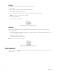
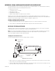
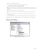
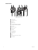
Table Of Contents
- Digital Sentry® DS ControlPoint
- Contents
- List of Illustrations
- Description
- Installing the Software
- DS ControlPoint Overview
- Operation
- Live
- Full Screen
- Quick Review
- Manual Record
- Snapshot
- Camera Groups
- Printing Images from Video Panes
- Entering a Motion Mask for Sarix Cameras
- Video Pane Borders
- Removing Video from a Window
- Manage OSD Settings
- Image Adjustments
- Enable On-Screen Pan/Tilt/Zoom
- Enable Digital Zoom
- PTZ Controls
- Alarm Page
- Pause Notification
- Search
- PTZ Cameras
- Appendixes

56 C3674M-L (6/15)
3. Remove the cover from the KBDKIT or KBDKIT-X wall block.
4. Connect the transmission wires from the receiver (Spectra
®
or Esprit
®
system) to the wall block.
a. Connect RX+ from the receiver/driver to TX+ (terminal 1) on the wall block.
b. Connect RX– from the receiver/driver to TX– (terminal 2) on the wall block.
NOTE: Communication to the keyboards is RS-422. The maximum cable distance for RS-422 communication over a 24-gauge wire is 1,219
meters (4,000 feet). It is recommended that you use shielded twisted pair cable that meets or exceeds the basic requirements for EIA RS-
422 applications.
5. At the wall block, wire the transformer to pins 3 and 4. Polarity is not important.
6. Replace the cover on the wall block. A double-sided sticky pad is provided to mount the wall block. Secure the wall block to a suitable
surface.
7. Set the keyboard DIP switches to the Pelco D or Pelco P protocol. For DIP switch settings, refer to the KBD300A Operation manual.
8. Connect the keyboard data cable.
9. Connect the KBDKIT or KBDKIT-X transformer to a suitable outlet. The LED display shows number 1, which is the default camera number.
10. Test for proper operation (refer to the programming and operation sections of the KBD300A Universal Keyboard Installation/Operation
manual).
Setup Option 2: Using the USB Adapter
1. Select the Device Manager under Computer Management.
Figure 55. Selecting the Device Manager