Digital Sentry Hardware For DSSRV2 and DS-CPPC Models INSTALLATION MANUAL C4693M-C | 10/14
Contents Important Notices . . . . . . . . . . . . . . . . . . . . . . . . . . . . . . . . . . . . . . . . . . . . . . . . . . . . . . . . . . . . . . . . . . . . . . . . . . . . . . . . . . . . . . . . . 4 Regulatory Notices . . . . . . . . . . . . . . . . . . . . . . . . . . . . . . . . . . . . . . . . . . . . . . . . . . . . . . . . . . . . . . . . . . . . . . . . . . . . . . . . . . . . 4 Radio and Television Interference . . . . . . . . . . . . . . . . . . . . . . . . . . . . . . . . . . . . . . . . .
Enabling SNMP Services . . . . . . . . . . . . . . . . . . . . . . . . . . . . . . . . . . . . . . . . . . . . . . . . . . . . . . . . . . . . . . . . . . . . . . . . . . . . . . . . . . . 28 Enabling Serial Ports in the BIOS . . . . . . . . . . . . . . . . . . . . . . . . . . . . . . . . . . . . . . . . . . . . . . . . . . . . . . . . . . . . . . . . . . . . . . . . . . . . 29 Digital Sentry Port Assignments . . . . . . . . . . . . . . . . . . . . . . . . . . . . . . . . . . . . . . . . . . . . . . . . . .
Important Notices Regulatory Notices This device complies with Part 15 of the FCC Rules. Operation is subject to the following two conditions: (1) this device may not cause harmful interference, and (2) this device must accept any interference received, including interference that may cause undesired operation. Radio and Television Interference This equipment has been tested and found to comply with the limits of a Class A digital device, pursuant to Part 15 of the FCC rules.
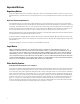
Package Contents Figure 1: Package Contents 1 System Hardware 2 USB Key: Might include installer software, a recovery image, and the installation and operation manuals. 3 Accessory Pack 4 Hard Drive Pack (hard drives in carriers) 5 Standard USB Keyboard (1 ea. for workstation models only) 6 Rack Mount Kit (1 ea.
Figure 2: Accessory Pack Contents 1 Standard USB Mouse (1 ea.) 2 Bezel Keys (2 ea.) 3 Standard US Power Cord (1 ea.) 4 Power Cord (based on country designation, 1 ea.) NOTE: Units shipped to China do not include power cords. 5 Chassis Handles (2 ea.); includes Phillips screws for installation. 6 Rubber Feet (4 ea.) Figure 3: Rack Mount Kit Contents 1 Sliding Mounting Brackets (2 ea.) 2 Rear Mount Rails (2 ea.), Front Mount Rails (2 ea.) 3 L-Shaped Plate Nuts (4 ea.) 4 M5*8L-H2.
Product Overview: Front Figure 1: Server Models: Front Panel Layout (Bezel Open) Figure 2: Workstation Models with-DVD: Front Panel Layout (Bezel Open) Figure 3: Front Bezel Indicators (Bezel Closed) 1 Unit Status • Green: The unit is functioning normally. • Flashing green: The unit is starting or shutting down. • Amber: The unit is nearing operational thresholds; maintenance is recommended. • Red: The unit is in an error condition.
4 Software Status • Green: The software is operating normally. • Amber: A minor software malfunction is detected (for example, an excessive network packet loss). • Red: A fatal software error has occurred (for example, ceasing to record). 5 Power Button • Push the power button to turn the unit on or off. • Push and hold the power button for a hard shutdown. 6 Drive Status • Flashing green: The read or write activity on a specific hard drive. • Solid red: A problem exists with the hard drive.
Product Overview: Rear Figure 1: Rear Panel Layout 1 Rear Chassis Fan 2 Power Receptacle 3 VGA Port Ethernet Ports 4 • Network Port 1 (left is primary) • Network Port 2 (right is secondary) 5 Expansion Slots 6 Serial Ports 7 Reserved (do not use) 8 Audio Output 9 Audio Input 10 USB 3.0 Ports 11 USB 2.
Product Serial Number Label Placement Product serial number labels identify a unit and its factory configuration if it should require service. Three labels citing a serial number are attached to the unit. • One label is attached to the upper-right corner of the rear of the unit. • A second, smaller label is attached to the inside left of the bezel. • A third set of labels is provided to attach to another product location that will not be obscured by installation.
Installing a DSSRV-RAID Controller Card The unit must be turned off, unplugged, and the chassis cover open before you can install hardware. DSSRV-RAID is an internal controller card that can be installed in DSSRV2 and DSSRV2-DVD units to manage your video storage in a RAID 5 array. A RAID 5 array requires at least three drives. One drive in the array is used for parity, reducing net storage capacity by one drive.
5. Lift the backplanes, and disconnect the SATA cables from each backplane. Do not disconnect the power cables. Remove the SATA cables from the chassis. Figure 3: Disconnecting the SATA Cables 6. Connect the multilane SATA cables to the appropriate connectors on the backplanes (refer to Figure 4). NOTE: Two sets of multilane SATA cables are supplied. The first set is numbered P1 to P4. The second set is numbered P5 to P6.
8. Insert and tighten the two screws on the top of each backplane. 9. Unscrew and remove the metal filler bracket for the PCIe x 16 slot. Figure 4: Removing the PCIe x 16 Filler Bracket 10. Replace the RAID card’s high-profile bracket with the supplied low-profile bracket. 11. Align the card with the PCIe x 16 slot. Gently press down on the card so that it is properly seated in the PCIe x 16 slot. Insert and tighten the metal bracket screw to secure the card.
12. Run the multilane SATA cables through the slot on the inside left of the unit. Figure 6: Running the Cables Through the Cable Slot 13. Connect the other end of the P5 cable to the motherboard for the optical drive on the DSSRV2-DVD. 14. Connect the multilane SATA cable plugs to the 4-lane connectors on the card. NOTE: The bottom DS-SRV-RAID connector (SAS_1) must be used for the first set of drives (HD1 to HD4).
Re-Imaging the Unit A USB key containing the software image is shipped with the unit. You must re-image the unit after installing an optional DSSRV-RAID controller card. NOTE: If burning the ISO image to a DVD, you must use a dual-layer DVD. DS-SRV2-RD models have the RAID card installed. Use the USB key packaged with the DS-SRV2 system to perform an image recovery. 1. Shut down the unit. 2. Insert the USB key. 3. Turn on the unit. 4.
Installing the SCSI Card Disconnect the power source before opening the chassis and installing or removing any expansion cards or other hardware. 1. Unscrew and remove the bracket for the PCIe x 16 slot. Set the screw aside. 2. Replace the high-profile bracket connected to the card with the low-profile bracket (supplied). 3. Align the card with the PCIe x 16 slot and gently press down on the card until it is firmly seated in the slot. Figure 1: Installing the SCSI Card 4.
Preparing the Unit for the SCSI Card 1. Shut down the unit. 2. Disconnect the power. 3. Disconnect any cables restricting access. 4. If mounted in a rack, unscrew the fasteners and carefully lift the unit out of the rack (two people may be required). 5. Place the unit on a flat surface with ample workspace. 6. Unlock and open the bezel. 7. Use a Phillips screwdriver to remove the case cover screws. 8. Remove the case cover by lifting it up. Set aside the case cover.
Installing an ENC5400 Capture Card The unit must be turned off, unplugged, and the chassis cover open before you can install the RAID controller. The ENC5400 capture card comes in 2- and 4-port models. The 2-port, primary card fits the unit’s PCIe x16 slot, and the secondary card, used for 4-port installations, fits the PCI slot to the left of the PCIe x16 slot. 1. Unscrew and remove the metal filler bracket for the PCIe x16 slot. 2. Align the card with the PCIe x16 slot. 3.
Installing a 4-Port Capture Card 1. Unscrew and remove the metal filler bracket for the PCI slot to the left of the PCIe slot where the 2-port card is installed. 2. Align the card with the PCI slot. 3. Gently press down on the card so that it is properly seated in the PCI slot. 4. Connect the 2- and 4-port cards using the 20p flat cable (supplied). Figure 2: Installing a 4-Port Capture Card 5. Insert and tighten the metal bracket screw to secure the card.
Mounting in a Rack Do not block slots and openings in the cabinet. These provide ventilation to prevent the unit from overheating. Never place the unit near or over a radiator or heat register. When placing the unit in a rack, be sure to provide proper ventilation. 1. Install the chassis handles: a. Align the screw holes on the chassis handles and the chassis. b. Insert and tighten the four 10-32 x 0.5-inch Phillips flat head screws with a Phillips screwdriver. 2.
Figure 3: Attach the L-Shaped Mounting Brackets 6. Attach the front and rear L-shaped brackets to the rack. Make sure the rails are mounted back to back. Use two M5*8L-H2.5 round head nickel screws for each bracket. The mounting brackets are identical and can be used on either side of the rack. a. b. c. d. Position the ear of the front L-shaped bracket and an L-shaped plate nut against the inside front of the equipment rack.
Figure 5: Install the Unit in the Rack Figure 6: Align the Chassis Bracket and the Sliding Bracket 9. 22 Insert and tighten two M5*8L-H2.5 round head nickel screws above and below the chassis handles to secure the unit in the rack.
Installing the Hard Drive Array After securely mounting the Hard Drive Array in the rack, install the hard drives. Place the hard drives into the bays in the correct order. When replacing a drive in a RAID array, you should rebuild the array before operating. If another drive fails before the array is rebuilt, the array will go offline and data loss will occur. WARNING: The hard drive parts and assemblies are susceptible to damage by Electrostatic Discharge (ESD).
Connecting an ENC5516 1. Ensure the unit is powered off. 2. Connect the dual-connector end of the DSSRV Data cable (ordered separately) to the unit’s primary capture card. 3. For 4-port connections, connect the dual-connector end of the DSSRV data cable to the unit’s secondary capture card. 4. Connect the other end of the DSSRV Data cable to each ENC5516.
Connecting an Uninterruptible Power Supply While UPS units supply backup battery power, the unit works in conjunction with the SmartUPS from APC. The SmartUPS signals the unit to begin a graceful shutdown if the UPS standby power falls below a specific threshold. 1. Shut down the unit. 2. Connect a power cord from the unit power supply to a standard wall outlet. 3. Connect a power cord from the UPS to a standard wall socket or other power source. 4.
Connecting to the Network The primary network interface card (NIC) must be active when using the License Key Entry program to add or update IP camera licenses. 1. Connect one end of an Ethernet cable one of the unit’s network interfaces. 2. Connect the other end of the cable to an available Gigabit Ethernet port. NETWORK SECONDARY Figure 1: Network Cable Connection Connecting the Power Supply 1. Connect the power cord to the unit’s power connector. 2.
Shutting Down the Unit Use an orderly shutdown for the unit to close files and power down. Use the immediate shutdown in an emergency or when there is not enough time for an orderly shutdown. Orderly Shutdown 1. Click Start. 2. Click Shut Down. Immediate Shutdown 1. Unlock and open the bezel. 2. Press and hold the power button until the unit shuts down. 3. Close and lock the bezel.
Enabling SNMP Services The Windows SNMP service is turned off by default. You must enable the SNMP service to issue SNMP requests or receive traps from the unit. The Digital Sentry MIB files are located on the Digital Sentry recorder at C:\Program Files (x86)\Pelco\Health Monitor\MIB • DigitalSENTRY-Base-MIB.MIB • Integral-Tech-SMI.MIB Consult the documentation for your SNMP manager for information about loading MIB files. 28 1. Click Start.
Enabling Serial Ports in the BIOS 1. Turn the unit on. If the unit is already on, restart it. 2. Press the Delete key repeatedly to access the BIOS. 3. Go to the Advanced menu. 4. Select NCT6776F Super IO Configuration. Press Enter. 5. Select the serial port you want to enable. Press Enter. 6. Select Serial Port from the menu. Press Enter. 7. Select Enabled from the menu. Press Enter. 8. Press Esc, and repeat the steps above to enable other serial ports. 9.
Digital Sentry Port Assignments Table A: DS Port Assignments 30 Port Assignment 25 TCP SMTP: Used to send email; can be blocked if not using the DSAdmin Email Notification feature 123 UDP NTP: Used by the Windows Time Service; can be blocked 137 TCP/UDP NETBIOS: Name Service 445 TCP/UDP Microsoft-DS: Used by the NET TIME/SET command; used in the scheduled task setup by FLTime 1433 TCP Off-box SQL server 1434 UDP Off-box SQL server 2000 TCP Remotely anywhere: Can be blocked if not used 1777
Troubleshooting If the following instructions fail to solve your problem, contact Pelco Product Support at 1-800-289-9100? (USA and Canada) or+1-559-292-1981 (international) for assistance. Be sure to have the serial number available when calling.?Do not try to repair the unit yourself. Leave maintenance and repairs to qualified technical personnel only. Table A: Troubleshooting Problem Possible Causes Suggested Solutions Power turned off. Check that the power indicator is lit Faulty cable connections.
Technical Specifications Hardware Specifications Processor Intel® Xeon® E3-1275 v3 Internal Memory 8 GB DDR3 non-ECC RAM; 16 GB DDR ECC RAM for DSSRV2-RD models Operating System Windows 7 Ultimate 64-bit SP1 User Interface Graphical User Interface, DS ControlPoint Internal Storage DSSRV2 500 GB, 4 TB, 8 TB, 12 TB, 16 TB, or 20 TB DSSRV2-DVD 500 GB, 4TB, 8 TB, 12 TB, or 16 TB DSSRV2-RD 12 TB, 16 TB, 20 TB, or 24 TB DS-CPPC 4 TB Optical Drive DVD±RW (DSSRV2-DV models only) USB Ports 3 USB 2
Network Interface 2 Gigabit Ethernet RJ-45 port (1000Base-T) Front Panel Buttons Indicator Unit Status Green, amber, red Primary Network Green, amber, red Secondary Network Green, amber, red Software Status Green, amber, red (based on diagnostics) Hard Disk Status Green, red, off (behind bezel) Power Power Input 100 to 240 VAC, 50/60 Hz, autoranging Power Supply Internal Power Consumption Operating Maximum 100 VAC 160 W, 1.60 A, 547 BTU/H 115 VAC 160 W, 1.
Models The following table describes DSSRV2 and DS-CPPC model numbers. For example, a 12 TB DSSRV2 unit with a power cord for the United Kingdom is DSSRV2-120-UK.
Certifications CE, Class A FCC, Class A UL/cUL Listed S-Mark for Argentina CCC C-Tick Standards/Organizations Pelco is a member of the MPEG-4 Industry Forum Pelco is a member of the Universal Plug and Play (UPnP) Forum, Steering Committee Pelco is a member of the Universal Serial Bus (USB) Implementers Forum Pelco is a contributor to the International Standards for Organization / Electrotechnical Commission (ISO/IEC) Joint Technical Committee 1 (JTC1), “Information Technology,” Subcommittee 29, Working Gro
Pelco by Schneider Electric 3500 Pelco Way Clovis, California 93612 USA (800) 289-9100 Tel (800) 289-9150 Fax +1 (559) 292-1981 International Tel +1 (559) 348-1120 International Fax www.pelco.com Pelco, the Pelco logo, and other trademarks associated with Pelco products referred to in this publication are trademarks of Pelco, Inc. or its affiliates. ONVIF and the ONVIF logo are trademarks of ONVIF Inc. All other product names and services are the property of their respective companies.