
Installation Manual
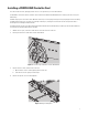
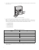

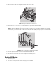
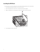
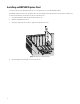
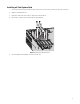
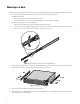
Table Of Contents
- Digital Sentry Hardware
- Contents
- Important Notices
- Package Contents
- Product Overview: Front
- Product Overview: Rear
- Placing on a Desktop
- Product Serial Number Label Placement
- Installing a DSSRV-RAID Controller Card
- Installing the SCSI Card
- Installing an ENC5400 Capture Card
- Mounting in a Rack
- Installing the Hard Drive Array
- Connecting an ENC5516
- Connecting an Uninterruptible Power Supply
- Connecting to the Network
- Connecting the Power Supply
- Connecting the Power Supply
- Shutting Down the Unit
- Enabling SNMP Services
- Enabling Serial Ports in the BIOS
- Digital Sentry Port Assignments
- Troubleshooting
- Technical Specifications

12
5. Lift the backplanes, and disconnect the SATA cables from each backplane. Do not disconnect the power cables. Remove the SATA
cables from the chassis.
Figure 3: Disconnecting the SATA Cables
6. Connect the multilane SATA cables to the appropriate connectors on the backplanes (refer to Figure 4).
NOTE: Two sets of multilane SATA cables are supplied. The first set is numbered P1 to P4. The second set is numbered P5 to P6.
The P5 cable is attached to the backplane for the optical drive and the P6 cable is unattached. Each cable has a different length,
and the connectors are right-angle connectors for nesting. The multilane SATA cable lengths are as follows:
• P1: 317.5 mm (12.5 inches)
• P2: 330.0 mm (13.0 inches)
• P3: 444.5 mm (17.5 inches)
• P4: 457.0 mm (18.0 inches)
• P5: 571.5 mm (22.5 inches)
• P6: 585.0 mm (23.0 inches)
7. Align each backplane with the two guide pins located at the bottom of the backplane slot. Ensure that all cables are cleared before
seating the backplane.
Table A: Multilane SATA Cable Connections
Connect To
First Set of Cables
P1 HD1
P2 HD2
P3 HD3
P4 HD4
Second Set of Cables
P5
P6
*DSSRV2-DVD uses only P5 in the second set of cables for the optical drive.