
Installation Manual
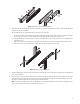
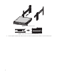
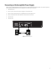
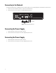
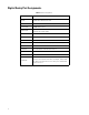
Table Of Contents
- Digital Sentry Hardware
- Contents
- Important Notices
- Package Contents
- Product Overview: Front
- Product Overview: Rear
- Placing on a Desktop
- Product Serial Number Label Placement
- Installing a DSSRV-RAID Controller Card
- Installing the SCSI Card
- Installing an ENC5400 Capture Card
- Mounting in a Rack
- Installing the Hard Drive Array
- Connecting an ENC5516
- Connecting an Uninterruptible Power Supply
- Connecting to the Network
- Connecting the Power Supply
- Connecting the Power Supply
- Shutting Down the Unit
- Enabling SNMP Services
- Enabling Serial Ports in the BIOS
- Digital Sentry Port Assignments
- Troubleshooting
- Technical Specifications

21
Figure 3: Attach the L-Shaped Mounting Brackets
6. Attach the front and rear L-shaped brackets to the rack. Make sure the rails are mounted back to back. Use two M5*8L-H2.5 round
head nickel screws for each bracket.
The mounting brackets are identical and can be used on either side of the rack.
a. Position the ear of the front L-shaped bracket and an L-shaped plate nut against the inside front of the equipment rack. Align
the two center holes in the ear of the L-shaped bracket and L-shaped plate nut with the holes in the rack.
b. Using two M5*8L-H2.5 round head nickel screws, insert and tighten the screws from the outside of the rack, pointing toward
the back of the rack.
c. Adjust the rails to the correct depth of the equipment rack by sliding the rear-mount rail to the back of the equipment rack.
d. Repeat the previous steps to attach the rear L-shaped bracket and L-shaped plat nut to the rack.
Figure 4: Attach the Brackets to the Rack
7. Tighten the M4*6L-H2.5 round head nickel screws that are attached to the front- and rear-mount rails which were left untightened
earlier in the installation.
8. Place the unit onto the mount rails by sliding the chassis brackets onto the rails. Align the chassis brackets with the first slot on the
sliding brackets when installing the unit. This will ensure that the two brackets are aligned properly when sliding the unit in and
out of the rack. It might require two people to lift and slide the unit into place.
NOTE: To pull the unit completely out of the rack, pull the unit out of the sliding bracket until it locks into place, and then press the
release levers on either side of the chassis bracket to release the unit.