O P E R AT I O N / C O N F I G U R AT I O N DX4104 Series Digital Video Recorder Server Software Application C4631M (11/09)
C4631M (11/09)
Contents Description . . . . . . . . . . . . . . . . . . . . . . . . . . . . . . . . . . . . . . . . . . . . . . . . . . . . . . . . . . . . . . . . . . . . . . . . . . . . . . . . . . . . . . . . . . . . . . . . . . . . . . . . . . 7 Remote Client Software Applications . . . . . . . . . . . . . . . . . . . . . . . . . . . . . . . . . . . . . . . . . . . . . . . . . . . . . . . . . . . . . . . . . . . . . . . . . . . . . . . . . 7 Product Overview . . . . . . . . . . . . . . . . . . . . . . . . . . . . . .
Linking Menu . . . . . . . . . . . . . . . . . . . . . . . . . . . . . . . . . . . . . . . . . . . . . . . . . . . . . . . . . . . . . . . . . . . . . . . . . . . . . . . . . . . . . . . . . . . . . . . . . . . 40 Alarm Input Setup . . . . . . . . . . . . . . . . . . . . . . . . . . . . . . . . . . . . . . . . . . . . . . . . . . . . . . . . . . . . . . . . . . . . . . . . . . . . . . . . . . . . . . . . . . . 40 Motion Detection Setup . . . . . . . . . . . . . . . . . . . . . . . . . . . . . . . . . . . .
List of Illustrations 1 2 3 4 5 6 7 8 9 10 11 12 13 14 15 16 17 18 19 20 21 22 23 24 25 26 27 28 29 30 31 32 33 34 35 36 37 38 39 C4631M (11/09) Application Window . . . . . . . . . . . . . . . . . . . . . . . . . . . . . . . . . . . . . . . . . . . . . . . . . . . . . . . . . . . . . . . . . . . . . . . . . . . . . . . . . . . . . . . . . . . . . . . 8 GUI Toolbar . . . . . . . . . . . . . . . . . . . . . . . . . . . . . . . . . . . . . . . . . . . . . . . . . . . . . . . . . . . . . . . . . . . . . . .
List of Tables A B C D E F G H I 6 Supported PTZ Protocols. . . . . . . . . . . . . . . . . . . . . . . . . . . . . . . . . . . . . . . . . . . . . . . . . . . . . . . . . . . . . . . . . . . . . . . . . . . . . . . . . . . . . . . . . . . 29 Resolution and Image Rate. . . . . . . . . . . . . . . . . . . . . . . . . . . . . . . . . . . . . . . . . . . . . . . . . . . . . . . . . . . . . . . . . . . . . . . . . . . . . . . . . . . . . . . . . 30 Resolution and Image Rate. . . . . . . . . . . . . . . . . .
Description The DX4104 Series digital video recorder (DVR) is designed for the entry-level market. The unit provides one to four camera inputs, powerful video storage management with efficient H.264 compression, multi-event recording, a quick and easy-to-use common user interface, greater internal storage (up to 2 TB), and network connectivity for up to 100 units. The DX4104 replaces the traditional VCR and multiplexer combination and can be used in stand-alone or networked installations.
Product Overview APPLICATION WINDOW The DX4104 is accessed through the graphical user interface (GUI). Use the mouse, remote control, or front panel controls to operate and configure the unit. This section describes the application window, GUI toolbar, Setup menu, PTZ control, and on-screen keyboard. NOTE: This manual describes how to operate and administer the unit using the mouse.
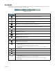
GUI TOOLBAR The GUI toolbar is used to access the Setup menu, dialog boxes, and controls that allow you to operate and configure the DVR. You can use the mouse to easily and quickly change settings and to operate the system. Figure 2. GUI Toolbar Status: Shows the current date and time. Setup: Displays the Setup men: Camera, Record, Display, Linking, Network, and System. Search: Opens the Search menu to select the following search modes: Date/Time, Event Search, and Bookmark Search.
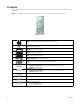
PTZ CONTROL The PTZ control is available for cameras that support PTZ functions using Pelco P and D protocols. It is also available for supported third-party dome cameras. NOTE: When operating third-party cameras, the PTZ control supports the up, down, left, right, zoom in, and zoom out functions. Figure 3. PTZ Control Move: Pans and tilts the camera in the direction of the selected arrow. Exit: Closes the PTZ control. ZOOM ZOOM: Zooms the camera in and out. FOCUS FOCUS: Adjusts the camera focus.
ON-SCREEN KEYBOARD The unit provides an on-screen keyboard to perform the following functions: • Select a user name and type a password to log on to the unit • Create camera names • Create holiday schedule names • Assign TCP/IP settings (IP address, subnet mask, and so forth) • Set up mail accounts • Assign emergency agent IP addresses • Create user accounts Figure 4 shows the on-screen keyboard for logging on to the unit.
Operation WARNING: Before you use the DX4104 to record video, refer to Figure 5 and read the Hard Disk Option Partition Notification. Figure 5. Hard Disk Option Partition Notification UNIT STARTUP AND SHUTDOWN 1. To start the unit, connect the power cord to a power supply. The DX4104 application window and the GUI toolbar appear (refer to Application Window on page 8 and GUI Toolbar on page 9). 2. To shut down the unit, disconnect the power cord from the power supply.
WORKING IN THE APPLICATION WINDOW By default, the toolbar is displayed at the bottom of the application window. It cannot be moved to a different location. TOOLBAR DISPLAY To hide or display the toolbar: 1. Right-click a pane in the application window. The shortcut menu appears. Figure 6. Application Window Shortcut Menu 2. Click “Control bar On/Off.” VIDEO DISPLAY You can adjust the video display (brightness, contrast, and color) at the application window.
MOTION AREA SELECTION You configure the motion area at the application window. Use the bounding outline (dotted rectangle) to select multiple areas. Selecting a Motion Area To select a motion area: 1. From the application window, click a channel pane. A white border highlights the selected pane. 2. Right-click the selected pane. The shortcut menu appears. 3. Click Motion. 4. Drag the bounding outline over an area (left to right). The selected cells are highlighted in green. Figure 7.
INSTANT RECORDING AND PLAYBACK The instant recording feature allows you to start a manual recording session immediately from the live view mode. Initiate the instant recording mode for channels that are scheduled for normal, alarm, or motion recording. Instant recording is the highest priority recording event. Observe the following instant recording conditions: • Instant (or normal) recording cannot start if the following conditions exist: – Video loss is displayed for the channel.
INSTANT PLAYBACK The unit supports two playback modes, instant playback and playback. Instant playback is initiated from the live view mode. The DVR simultaneously plays back and records live video. Live quad view is not available during instant playback. Instant playback video is displayed in a single pane. For information about the playback mode, refer to Playback on page 21. The instant playback mode supports the following features: • Playback: Video is played back for one channel at a time.
PTZ IN LIVE VIEW The DVR displays a control for operating PTZ cameras. The PTZ option must be configured for each camera to use the PTZ control. • Programming: To program or clear presets, preset tours, and patterns, the SET button must be engaged. While in PTZ programming mode, multiple presets can be programmed. • Activating a PTZ feature: To activate presets, tours, and patterns, the SET button must be disengaged.
ACTIVATING PATTERNS A pattern is a user-defined, viewable camera path with a specified beginning and end. Patterns are made up of a sequence of standard pan/tilt and lens commands. Patterns are stored in the internal memory of the PTZ device that is connected to the DX4104. Depending on the type and configuration of the PTZ device, the DX4104 can address up to four unique PTZ patterns.
PTZ PATTERNS Programming a Pattern 1. Click SET. The camera is now in the programming mode. 2. Click a number representing the pattern (1 to 4). 3. Click PATTERN. 4. Move the camera through a series of movements using the on-screen PTZ and focus controls. a. Click the Move buttons . b. Click ZOOM, and then click FOCUS. 5. When you have finished programming the pattern, click PATTERN, and then click SET. 6. To verify that the pattern can be activated, click the pattern number, and then click PATTERN.
ACKNOWLEDGING AN ALARM OR MOTION EVENT The DX4104 allows you to manually acknowledge an event state that has activated a relay output. By default, the DVR’s output relay is turned off when the post-alarm time expires. Acknowledging an alarm or motion event does not end alarm or motion event recording. The post-alarm time determines the time period for alarm recording. For information about configuring the relay off setting, refer to Relay Output Setup on page 41.
SYSTEM INFORMATION The System Information option displays system and hard disk information. To view all system information, you must be logged on to the unit. To view system information, click Information . The System Information screen displays all system information. Figure 12. Viewing System Information: Full Details Use the Pelco serial number when corresponding with Pelco about your unit. The MAC address is an internal number.
SEARCH VIDEO The search feature allows you to use the date/time, event, and bookmark search feature to find and play back video stored to the unit. You can use the date/time and event search features to view backed up video stored on a USB or CD/DVD media. To display the search menu, click the Search icon . Figure 13. Search Menu DATE/TIME SEARCH AND PLAYBACK You can search video data based on a calendar date (month, day, and year) and the time of day.
5. Click the Time box, and then select a time. 6. Click the number box to select a playback channel. Figure 15. Selecting Playback Time and Channels 7. Click Play. 8. To exit playback, click the Stop icon . DST DATE/TIME SEARCH AND PLAYBACK If the unit is configured for Daylight Saving Time (DST), the DVR uses a different approach to store and display video. When DST ends, the DVR’s internal time automatically adjusts backward one hour.
Figure 17. Selecting Playback Time and Channels 4. Click the Time settings box, and then right-click the box to enter a time setting (refer to Figure 17). You can also click and drag the time line to enter a time. 5. Click Play. The “Select data” dialog box appears. 6. Select the time period from which to play back data: • Video recorded before daylight saving ends: (1) Click the settings box, and right-click the box to select “DST on.” (2) • Click OK.
BOOKMARK SEARCH The bookmark search feature allows you to search for and play back bookmarked video. You can also bookmark playback video (instant or search). This feature is not supported for data backed up to external media. NOTE: The DX4104 supports the play , pause forward, end playback controls are not supported. , and stop buttons when playing back exported video. The reverse start, reverse, Bookmarking Instant Playback Video 1. From the application window, click a pane. 2.
EXPORTING VIDEO The DX4104 allows you to export data to CD/DVD or USB media. You can view the exported video on the unit or at the remote client computer. NOTES: • The erase and format features allow you to format media for use with the DVR. Although media can be formatted on a PC, Pelco recommends that you format the media on the DVR to guarantee functionality. For information about formatting media, refer to Erasing and Formatting Media on page 57.
Configuration NOTE: The DX4104 is preconfigured for immediate operation. For a list of system defaults, refer to Appendix A: DX4104 Factory Defaults on page 60. Only administrator-level users can configure the DVR. The Setup menu allows you to access the Camera, Schedule, Display, Linking, Network, and System menus to configure the DX4104 for your specific application requirements (refer to Figure 21). You must be logged on with administrator-level permission to configure the unit.
CAMERA MENU To access the Camera menu options, click Camera. Figure 22. Camera Menu The DX4104 allows you to configure the following properties settings for each camera: • Channel: Selects the channel (01 to 04) for configuration. • Name: Allows you to create a unique name for each camera. • Covert: Allows a camera to be configured, viewed, and operated only by users who are logged on with administrator-level permission. • Audio: Associates the audio input (1 to 4) with the selected channel.
PTZ MODE The DX4104 supports up to four serial PTZ cameras. Multiple PTZ cameras can be connected and controlled individually by daisy-chaining the camera connections. The unit also allows you to assign each camera a PTZ control address. The DX4104 allows you to configure the following PTZ settings for each camera: • Channel: Selects the channel (01 to 04) for PTZ configuration. • Port: Sets the communication port for the camera: NONE, DATA1, or DATA2.
VIDEO FORMAT WARNING: If you change the video format, the unit will delete all existing data, reformat the HDD, and restart. 1. From the Camera menu, click Video. 2. Click the Video Format box, and then select NTSC or PAL. (NTSC is the default.) A warning message appears. 3. Click OK. The unit reformats the HDD and restarts automatically. NORMAL RECORD MODE The DX4104 allows you to configure the following recording settings for each camera: • Channel: Selects the channel (01 to 04) for configuration.
ALARM RECORD MODE You can configure each camera to record at a different resolution, quality, and image rate to capture alarm-triggered video. The unit also allows you to configure the prealarm and postalarm settings for each camera. Refer to Normal Record Mode on page 30 for more information. You must configure the respective camera for alarm recording before the unit will respond to an alarm event. Refer to Schedule Menu on page 34 for more information.
MOTION RECORD MODE The unit supports multi-event recording. You can configure each camera to record at a different resolution, quality, and image rate to capture motion-triggered video. You must configure the respective camera for motion recording before the unit will respond to a motion event. Refer to Schedule Menu on page 34 for more information. The DX4104 allows you to configure the following motion recording settings for each camera: • Channel: Selects the channel (01 to 04) for configuration.
INSTANT MOTION RECORD MODE The unit allows you to manually start and stop the instant recording mode. You can configure each camera to record at a different resolution, quality, and image rate to capture instant recording video. The DX4104 allows you to configure the following instant recording settings for each camera: • Channel: Selects the channel (01 to 04) for configuration. • Resolution: Sets the resolution for the channel. The default is 352 x 240. Table E.
SCHEDULE MENU The scheduling feature allows you to create daily, weekly, and holiday schedules for each channel. Up to 10 different holiday schedules can be created. If a holiday schedule occurs on the same date as a weekday schedule, the holiday schedule will override the weekday schedule. You can manually start an instant recording mode (refer to Instant Recording and Playback on page 15). The instant record mode takes precedence over the current recording schedule.
COPYING SCHEDULES The DX4104 supports four methods for copying schedules: • Weekday (M to F): The schedule from the highlighted day is copied to the respective channels for every day of the week except Saturday and Sunday. • Weekend (Saturday and Sunday): The schedule from the highlighted day is copied to the respective channels for Saturday and Sunday only. • Day (Sun to Sat): The schedule for any day can be copied to any other day, all weekdays, or the weekend.
Copying By Channel 1. From the Schedule menu, click the source schedule day. 2. Click a source channel. Figure 25. Selecting a Source Channel 3. Click the “Ch copy” (channel copy) option. 4. Click each destination channel. Figure 26. Selecting the Destination Channels 5. Click OK. 6. Click Close. 7. Click OK. HOLIDAY SCHEDULES The unit supports up to 10 holiday schedules. When a holiday and a weekday schedule occur on the same date, the holiday schedule overrides the weekday schedule.
4. Click OK. The on-screen keyboard appears. Figure 28. Naming a Holiday Schedule 5. Click the settings box to enter the schedule name. 6. Click OK. The schedule appears. 7. Create a recording schedule for each channel. Figure 29. Creating a Holiday Recording Schedule for Each Channel 8. Click Close. 9. Click OK. Editing a Holiday Schedule 1. From the Schedule menu, click Holiday. 2. Click List. 3. Select a holiday recording schedule, and then click Edit. Figure 30.
4. Edit the holiday recording schedule settings for a channel. Figure 31. Editing a Holiday Recording Schedule 5. Click Close. 6. Click OK. Deleting a Holiday Schedule 1. From the Schedule menu, click Holiday. 2. Click List. 3. Select a holiday recording schedule, and then click Delete. 4. Click Close.
DISPLAY MENU To access the Display menu options, click Display. OSD (ON-SCREEN DISPLAY) The DX4104 allows you to configure the following display settings for the unit: • Language: Sets the unit display language. The default is English (United States). You must log on with administrator-level permission to change the language. • Channel Name: When set to ON, displays the channel name. • Channel Status: When set to ON, displays the channel status icons. To configure the OSD settings: 1.
LINKING MENU The Linking menu allows you to set up alarm inputs, motion inputs, and the relay output. NOTE: The prealarm and postalarm recording settings are configured in the normal recording option on the Camera menu. Refer to Normal Record Mode on page 30 for more information. ALARM INPUT SETUP The unit allows you to configure the following alarm input settings: • Input Channel: Selects the alarm input (01 to 04) for configuration. • Input Type: Alarms are programmed for normally open (N.O.
RELAY OUTPUT SETUP You can configure how the relay output is controlled: alarm acknowledge or post-alarm time. The relay out OFF setting does not control the actual alarm recording function. Turning off the relay output does not terminate the alarm recording mode. • Relay Off: – ALARM ACKNOWLEDGE: The relay output feature must be turned off manually. – POST-ALARM TIME: Turns off the relay output feature automatically when the post-alarm time expires.
NETWORK MENU You must configure the DVR network settings to use the following features: • Client software application: Allows you to operate and administer up to sixteen DX4104 servers. The DX4104 server supports up to five simultaneous connections when using the client and Web client applications. For more information about the remote client software application, refer to the DX4104 Client Operation/Configuration manual.
DDNS SETUP The DDNS feature uses the services provided by No-IP™. Prior registration with No-IP to obtain a user name and password is required before configuring the DVR. The DDNS feature uses port 8245 provided by No-IP. If the DVR is installed in a network that has a firewall, port 8245 has to be open to allow DDNS data to get through the firewall. For information about setting up the firewall, refer to your network administrator or network service provider.
• Mail Address (1 to 3): User’s e-mail address. Supports up to 24 characters including a to z, A to Z, numerals 0 to 9, and special characters. The SMTP server IP address, port number, user name, and password are optional settings. The DVR can send e-mail without using an SMTP server or MTA (message transfer agent). In certain cases, e-mail should be forwarded to a SMTP server. To set up the mail feature: 1. From the Network menu, click Mail. 2. Click the Notification box, and then select ON.
SYSTEM MENU The system settings should be configured before the unit is put into service. Some of the settings affect how video data is stored and backed up. The settings can also affect how the unit is operated and administered from a remote client application. • Date/Time: Establishes the time frame for configuring recording schedules and automated backup. Also provides the time stamp for recorded video, e-mail notifications, and emergency notifications.
NTP SETUP The unit’s internal time can be synchronized with an external time source using the Network Time Protocol (NTP) Date/Time configuration option. • NTP: Sychronizes the DVR’s time. This feature must be set to ON before the NTP server is selected. NOTE: If the NTP option is set to ON, the Date/Time option is unavailable. • Server: Allows you to select a public or private NTP server. The default setting is PUBLIC SERVER.
USER ACCOUNT SETUP User accounts can be added, changed, or deleted. By default, both the user name and password for user number 01 are admin; only the password can be changed. The user ID (admin) and Level (Administrator) for user 01 cannot be changed. A user account consists of the following settings: • Number: The unit supports 10 users (01 to 10). • ID: The user name is created by the system administrator and can have up to 23 characters. • Level: Defines the features that are available to the user.
Changing a User 1. From the System menu, click User. The default is 01. Figure 33. Changing the Default Administrator Password 2. Click the Password box. 3. Type the current password and click OK. 4. Type the new password and click OK. The new password must contain 4 to 8 characters. 5. Click Close. 6. Click OK. Adding a New User Only a user with administrator-level permissions can add, change, or delete users. Refer to User Account Setup on page 47 for more information. To add a new user: 1.
Deleting a User To delete a user: 1. From the System menu, click User. 2. Click the Number box to select an ID. 3. Click Delete. The user assigned to the selected ID is deleted. 4. Click Close. 5. Click OK. UPDATE SOFTWARE The update feature allows you to upgrade DVR software and add or upgrade PTZ protocols. The current DVR settings are not deleted or replaced during the update process. You can perform an update from either the USB drive or a network server.
Updating Over the Network To update over the network: 1. From the System menu, click Update. 2. Click the Selection box, and then select a setting. 3. Click the Method box, and then select NETWORK. 4. Click the Update Server box, and then type the update server IP address. 5. Click Update and click OK. 6. Wait while the system searches for the update server and starts the update process. After the update process is complete, the “Restart the System” dialog box appears. 7. Click OK to restart the unit.
• Format: Initializes all installed HDDs. The System Information dialog box lists the installed drives and their respective capacities. If you install a new drive, the system prompts you to format the drive. When you format the drive, all data on the drive is erased. • Overwrite: – ALL: When the normal and event partitions are full, the system will begin overwriting recorded video. The oldest recorded data is overwritten first. The default setting is ALL.
BACKUP SCHEDULE SETUP The backup feature allows you to perform an instant backup of recorded data. It also allows you to configure the system to perform an automatic backup of data on a scheduled basis. You must have administrator permissions for setting up and conducting backup procedures. The backup feature allows you to schedule how the DVR backs up recorded video data.
Instant Backup The instant backup feature allows you to manually back up data. The backup settings unique to the instant backup mode are as follows: • Schedule Start: Unavailable and is not used. • Time Range Date: Sets the date of the backup process. • Time Range Start: Sets the starting time (in hours and minutes) within the recorded data base where the backup process begins. • Time Range End: Sets the ending time (in hours and minutes) within the recorded data base where the backup process ends.
12. (Optional) To view the backup status: a. Exit the Setup menu. b. Click the System Information icon . Figure 37. Instant Backup Status Information c. 54 Click OK.
Weekly Backup Schedule The weekly backup feature allows you to perform an automatic backup of the current week’s data to a USB device only. The week begins at 00:00 hours on Monday and ends at 23:59 hours on Sunday. Data can be backed up for one or more days and from one minute to 24 hours. The unit can be configured to back up all, normal (instant and normal recorded video), or event-initiated (alarm and motion) recorded video. The weekly backup settings are as follows: • Device: USB device.
Daily Backup Schedule The daily backup feature allows you to perform an automatic backup of recorded data to a USB device. You can configure the time when the backup process starts and ends. The start and end times can be specified, and the DVR can be configured to back up all, normal (instant and normal recorded video), or event-initiated (alarm and motion) recorded video. The daily backup settings are as follows: • Device: USB media. • Schedule: Daily.
Erasing and Formatting Media The erase and format features allow you to format media for use with the DVR. Although media can be formatted on a PC, Pelco recommends that the media be formatted on the DVR to ensure optimal equipment function. The DVR does not support a weekly or daily backup to CD/DVD media. If you try to format a CD or DVD when the unit is configured for a weekly or daily backup, a warning message appears. For information about supported media, refer to Table G on page 52.
SYSTEM IR Remote ID The infrared (IR) ID feature allows you to transmit a unique IR Remote ID (01 to 09) from the remote control to one or more DVRs. Each DVR that is preconfigured with the transmitted ID can respond to and be operated by the remote control. DVRs with a different ID are disabled from responding to the remote control but are not disabled from normal operation.
Export/Import Configuration Settings NOTE: Resetting the DVR to its factory defaults deletes the customized settings. To save the customized settings, be sure to perform a configuration export before resetting the factory defaults. The export feature allows you to save the DVR configuration settings to a USB device. The import feature allows you to import the settings to quickly configure a DVR for operation. Multiple DVRs can be configured quickly using this method. Export Settings 1.
Appendices APPENDIX A: DX4104 FACTORY DEFAULTS NOTE: Resetting the DVR to factory defaults deletes the customized settings. To save the customized settings, be sure to perform a configuration export before resetting the DVR to the factory defaults. For information about exporting the configuration settings, refer to Export/Import Configuration Settings on page 59. Table H.
Table H. Factory Default Settings (Sheet 2 of 4) Menu Command Option Property Default Setting Factory Default Client Application Display OSD Language ENGLISH Yes Yes Channel Name ON Yes Yes Channel Status ON Yes Yes Main Monitor Dwell Time 2 SEC Yes Yes Spot Monitor Dwell Time 2 SEC Yes Yes Event Popup OFF Yes Yes Spot Channel 01 Yes Yes Input Channel 01 Yes Input Type N.O.
Table H.
Table H.
APPENDIX B: DX4104 OPERATION METHODS The manual describes how to use the mouse to operate and configure the unit. This appendix provides a quick tutorial for using the remote control and front panel controls to operate the unit. You can use any or a combination of all three methods. NOTE: The unit’s front panel LOGIN and arrow buttons are available for logging on to the unit. The remaining front panel controls are only available after you log on to the unit. Table I.
APPENDIX C: HARDWARE AND SOFTWARE UPGRADE POLICY Pelco’s representations regarding product features and performance are limited to those made in the specification sheet and product manuals at the time the product was manufactured. Pelco does not represent or warrant that any upgrades to product hardware or software will be made available in the future. When possible, Pelco will offer product upgrades to purchasers of its products.
APPENDIX D: RECOVERING THE ADMINISTRATOR PASSWORD 1. On the left side of the unit, locate and note the manufacturer’s serial number. 2. In the toolbar, locate and note the current date. 3. Contact Pelco Product Support to receive the administrator password: 4. Enter the password provided by Pelco Product Support: 66 a. On the toolbar, click Login b. Type the password. c. Click OK. . The on-screen keyboard appears.
PRODUCT WARRANTY AND RETURN INFORMATION WARRANTY Pelco will repair or replace, without charge, any merchandise proved defective in material or workmanship for a period of one year after the date of shipment.
www.pelco.com Pelco, Inc.