® DX2000 Digital Video Recorder Installation/ Operation Manual C690M-E (11/04) Pelco World Headquarters • 3500 Pelco Way, Clovis, CA 93612-5699 USA • www.pelco.
CONTENTS Section Page GENERAL . . . . . . . . . . . . . . . . . . . . . . . . . . . . . . . . . . . . . . . . . . . . . . . . . . . . . . . . . . . . . . . . . . . . . . . . . 5 IMPORTANT SAFEGUARDS AND WARNINGS . . . . . . . . . . . . . . . . . . . . . . . . . . . . . . . . . . . . . . . . 5 REGULATORY NOTICES . . . . . . . . . . . . . . . . . . . . . . . . . . . . . . . . . . . . . . . . . . . . . . . . . . . . . . . . . . . . . . DESCRIPTION . . . . . . . . . . . . . . . . . . . . . . . . . . . . . . .
INFORMATION BOXES . . . . . . . . . . . . . . . . . . . . . . . . . . . . . . . . . . . . . . . . . . . . . . . . . . . . . . 76 VIEWING LIVE VIDEO . . . . . . . . . . . . . . . . . . . . . . . . . . . . . . . . . . . . . . . . . . . . . . . . . . . . . . . . . . . 77 CONTROLLING THE CAMERA . . . . . . . . . . . . . . . . . . . . . . . . . . . . . . . . . . . . . . . . . . . . . . . . 77 CONTROLLING THE CAMERA TOUR FEATURE . . . . . . . . . . . . . . . . . . . . . . . . . . . . . . . . .
LIST OF ILLUSTRATIONS Figure 1 2 3 4 5 6 7 8a 8b 9 10 11 12 13 14 15 16 17 18 19 20 21 22 23 24 25 26 27 28 29 30 31 Page Rear Panel View . . . . . . . . . . . . . . . . . . . . . . . . . . . . . . . . . . . . . . . . . . . . . . . . . . . . . . . . . . . . Rear Panel Connections, DX2016 Models . . . . . . . . . . . . . . . . . . . . . . . . . . . . . . . . . . . . . . . . Data Connections . . . . . . . . . . . . . . . . . . . . . . . . . . . . . . . . . . . . . . . . . . . . . . . . . . . . . . . . . . .
GENERAL IMPORTANT SAFEGUARDS AND WARNINGS Observe the following WARNINGS before installing and using this product. 1. Read these instructions. 2. Keep these instructions. 3. Heed all warnings. 4. Follow all instructions. 5. Do not use this apparatus near water. 6. Clean only with dry cloth. 7. Do not block any ventilation openings. Install in accordance with the manufacturer’s instructions. 8.
REGULATORY NOTICES This device complies with Part 15 of the FCC Rules. Operation is subject to the following two conditions: (1) this device may not cause harmful interference, and (2) this device must accept any interference received, including interference that may cause undesired operation. RADIO AND TELEVISION INTERFERENCE This equipment has been tested and found to comply with the limits of a Class B digital device, pursuant to Part 15 of the FCC Rules.
There are four types of recordings: • Scheduled Recording This type is simply the days and times you wish to record. • Motion Recording You set up this type to record when motion is detected on selected cameras. The advantage of motion recording is that it lets you set a higher recording rate for better detail, but still conserves disk space.
MINIMUM PC REQUIREMENTS • • • • • • • Pentium®III processor Processing speed of 800 MHz 128 MB RAM Video resolution of 1024 x 768, 24-bit color Video card with 16 or more megabytes of RAM Windows® 2000, NT4.0 (SP6), XP Internet Explorer 5.
MODELS DX2008-160 8-channel duplex digital video recorder, 160 GB hard drive, 100-240 VAC, 50/60 Hz, NTSC/PAL DX2008-320 Same as DX2008-160, except has 320 GB of storage DX2008-480 Same as DX2008-160, except has 480 GB of storage DX2008-640 Same as DX2008-160, except has 640 GB of storage DX2016-160 16-channel duplex digital video recorder, 160 GB hard drive, 100-240 VAC, 50/60 Hz, NTSC/PAL DX2016-320 Same as DX2016-160, except has 320 GB of storage DX2016-480 Same as DX2016-160, except has 480
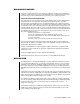
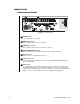
INSTALLATION REAR PANEL OVERVIEW 4 2 75 HZ 1 2 3 3 4 5 9 100-240~ 50/60HZ 200 WATTS MAX 6 7 1 75 8 9 HZ 10 11 12 13 N T NC SCS NNP R SOA E LS 5 ON OFF 1 2 3 4 5 6 7 9 10 11 12 13 14 ALARMS 8 1 8 COM 1 DEFAULT IP RESET COM 2 12 15 16 14 15 16 REL 1 REL 2 N C N O C N C N O C 6 TCP/IP 10/100 10 MON OUT 11 2 3 D A T A P O R T S 4 7 Figure 1. Rear Panel View 1 ON/OFF switch Use to toggle power on/off to unit.
8 Alarm inputs These two (DX2008) or four (DX2016) 8-pin inputs can be configured to be N.O. (normally open), N.C. (normally closed), or supervised. They are configured via a DIP switch mounted next to the connectors. Refer to the Connecting Alarms section for more information. 9 DIP switches The first two switches (counting from the left) on this four-position DIP switch determine alarm mode (supervised/unsupervised or normally open/normally closed).
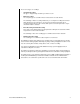
REAR PANEL CONNECTORS The components on the rear panel are shown in Figure 2. Making connections is explained in the installation procedures. NOTE: SEE DIP SWITCHES THIS SECTION.
POS TERMINAL PELCO DATA ADAPTER (DX2000DA) RS-232 ATM OR ATM ATM ATM NETWORK 1 2 D A T A PELCO DATA ADAPTER (DX2000DA) PELCO DATA ADAPTER (DX2000DA) POS TERMINAL RS-232 P O 3 R T S RS-422 RS-232 PV130 4 RS-422 ADAPTER (PV130) PELCO DVR DATA HUB (DX2000DH) PELCO DVR DATA HUB (DX2000DH) RS-422 RS-422 NOTE: SEE CONNECTING POS TERMINALS AND ATMs SECTION.
INSTALLATION STEPS Refer to Figures 2 and 3. NOTE: RS-232 cable length should not exceed 49 feet (15 meters). 1. Install the DVR. Install it in a rack using the supplied rack ears and hardware, place it on a flat surface, or mount the unit on a wall. Allow access to the rear of the unit. To mount the DX2000 on a wall, refer to Figure 4 and do the following: a. Using the supplied screws, attach the rack mount ears to the center holes on each side of the DVR. b.
2. Connect the cameras. Plug standard coaxial cables (not supplied) from the cameras into the top row of BNCs on the rear of the DVR. Camera 1 is the top left BNC. Set rear panel DIP switch 3 to the correct position (UP=NTSC, DOWN=PAL). Set the video termination switches to the proper setting: 75 ohms if no equipment is connected to the BNC looping connector; HZ if equipment is connected to the BNC looping connector. 3. Connect a video monitor (if desired).
9. Connect a PC. • If a PC will be connected directly to the DVR, connect it at the Ethernet port on the rear of the DVR using a T568A/B cross-over shielded CAT5 cable with shielded RJ-45 connectors (not supplied). The maximum length is 328 feet (100 m).
11. a. Change the default network settings if necessary. Do the following: • Connect the PC. Connect it at the Ethernet port on the rear of the DVR using a T568A/B cross-over shielded CAT5 cable with shielded RJ-45 connectors (not supplied). • Refer to the Changing the Default IP Address section. • Remove the PC. b. Connect to an Ethernet network (LAN/WAN).
e. Program general items. You must set the date and time. Refer to the General Information section. f. Name cameras. Refer to the Camera Names section. g. Set the times and days of the week for scheduled recording. Refer to the Record Schedule section. h. Program motion detection recording (if applicable). Refer to the Motion Recording section. i. Program event and alarm recording (if applicable). Refer to the Event And Alarm Recording section. j.
CONNECTING ALARMS On the rear panel of the unit are four 8-pin inputs. Every odd-numbered pin is an alarm pin while every even-numbered pin is a ground. These inputs can be configured to be N.O. (normally open), N.C. (normally closed), or supervised. • Unsupervised relay contacts are wired as either normally open or normally closed. Unsupervised modes are easily defeated and should not be used in critical situations when security is most important.
Unsupervised Alarm Input Configuration and Wiring Unsupervised relay contacts are not terminated. They are wired as either normally open or normally closed. Set switch 1 down. Set switch 2 up for normally closed (N.C.) or down for normally open (N.O.). Refer to Figure 6. Unsupervised modes are easily defeated and should not be used in critical situations when security is most important.
Supervised Alarm Input Configuration and Wiring Supervised mode activates an alarm if the current in a line falls outside a specified range. This blocks an attempt to defeat the alarm system by cutting a wire or through bypassing or shorting a section of the circuit. If the whole system is in supervised mode, then all inputs (including unused inputs) must be terminated with 10K resistors (not included). • If you want the alarm contacts to be N.O.
SUPERVISED, NORMALLY CLOSED IN THIS CONFIGURATION, TRANSISTOR "S" (THE SWITCH) IS BIASED FOR CONDUCTION AND WIRED IN SERIES WITH ITS 10K COLLECTOR RESISTOR. ALONG WITH THE INTERNAL 10K RESISTOR ON THE EQUIPMENT SIDE, THEY FORM A VOLTAGE DIVIDER NETWORK THAT LEAVES POINT "A" AT ABOUT 2.5V (WHICH IS MID-POINT IN THE "STAND-BY MODE" VOLTAGE RANGE SHOWN IN THE ALARM DIAGRAM). A HIGH CONTROL SIGNAL (TTL) GREATER THAN 50ms DURATION ACTIVATES NORMAL STAND-BY MODE.
UNSUPERVISED, NORMALLY CLOSED IN THIS CONFIGURATION, TRANSISTOR "S" (THE SWITCH) IS BIASED FOR CONDUCTION AND POINT "A" RESIDES CLOSE TO 0V. IF THE TRANSISTOR IS BIASED TO THE OFF STATE OR IF THE LINE IS CUT TO STOP CURRENT FLOW, POINT "A" RISES TOWARD 5V AND AN ALARM CONDITION. +5V NOTE: PIN NUMBERS REFER TO TYPICAL HEADER ALARM INPUT NUMBERS ON MATING PLUGS INPUT VOLTAGE A L A RM 2.
CONNECTING POS TERMINALS AND ATMs The DX2000 supports data input from up to 16 POS terminals or ATMs. The DVR provides options for connecting these devices using DX2000 data adapters. These optional adapters let you connect to RS-232 serial interfaces and optically isolate each device from the DX2000. In addition, the optional DX2000DH Data Hub provides a local connection for up to seven ATM or POS devices and delivers the transaction data to the DX2000 over a single cable.
POS Terminals • Direct Connection Connect a DX2000DA9 Data Adapter to the serial communications port of the POS terminal. Attach the RJ-45 cable (supplied with each adapter) from the adapter to any of the DX2000 data ports. • PIM Connection Connect the PIM to the POS terminal. Attach the RJ-11 cable (supplied with each PIM) from the PIM to any of the DX2000 data ports. • PV130 RS-422 Converter Connection Connect the PV130 to the POS terminal.
CONFIGURING YOUR PC To configure your PC: • PC Settings Turn on the PC. Change your PC’s display resolution to 1024 x 768 (if not already on this setting), change the color to 24 or 32 bit (if not already set), change to small fonts (if not already set). You can change these by navigating through Start, Settings, Control Panel, Display Properties, Settings tab, Advanced button, and General tab on your PC. You may need to hide the Taskbar at the bottom of the screen to see all of the DVR screen.
CHANGING THE DEFAULT IP ADDRESS To change the default IP address, do the following: 1. The network administrator must assign a new IP address and subnet mask. 2. Turn on the DVR. Turn on the PC. 3. Open Internet Explorer on your PC. Type the DVR’s default IP address (192.168.2.108:8004) in the Address box and press Enter. This lets the PC access the DVR. 4. In the Enter Network Password dialog box that appears, enter the default administrative ID (admin) and password (PELCOADM).
LOGIN You control the DVR through a PC. There are two levels of access to the DVR: user and administrative. The user level provides access to the DVR for viewing live and recorded images. The administrative level allows full access, including configuration capability. The logon passwords are set through configuration. With a brand new DX2000 or with a unit that has been totally reset, the default administrative ID is admin and the default administrative password is PELCOADM.
TIP: To access multiple DVRs, save addresses in the Favorites menu. As a DX2000 user/administrator/manager you can save the IP addresses of DX2000 sites you connect to or use in a file in the Favorites menu of your browser for future access. If you want to share those addresses with another site you can do so using the Import/Export Wizard in your Internet Explorer browser. Follow the instructions below. 1. In the browser’s File menu, click Import and Export. The Wizard welcome screen appears. 2.
QUICK GUIDE TO THE MENU STRUCTURE The following shows how the DVR’s screens are organized.
PROGRAMMING Programming lets you configure camera and alarm operation, set the system date and time, and define a password (among other things). Programming activities are accomplished through the Configuration menu. CAMERA NAMES Figure 11. Camera Names Screen This screen lets you give each camera a description, typically designating a viewing area such as lobby, front desk, etc. Do the following to name the cameras and designate their protocol. 1. Click the Configuration button. Click Camera Names.
RECORDING There are four types of recordings: 32 • Scheduled Recording This type is simply the days and times you wish to record. The configuration includes halfhour increments for every day of the week. The DVR can record all cameras continuously or can record selected cameras at selected times. For example, you can set up different camera schedules for weekdays and weekends, at nighttime and daytime. • Motion Recording You set up this type to record when motion is detected in selected camera views.
SCHEDULED RECORDING Figure 12. Record Schedule Screen NOTE: In order to maximize hard drive storage space, the DX2000 uses images from scheduled recording to display images for a transaction. To do this, you need to set scheduled recording appropriately (for example, at the right image rate, quality, etc.) and for all hours the cash register or ATM is operational.
Figure 13. Set Camera Screen 3. 4. 34 Do the following to select a range of time segments: a. Checkmark the starting time, hold down the Shift key, and then checkmark the ending time. The block changes color. b. Click the bar to the right of the check-marked starting time, hold down the Shift key, and then click the ending time’s bar. The block changes color. c. Click one of the bars in the marked block. The program displays the Set Camera screen (refer to Figure 13).
5. Under Record Rate, use the pull-down menu to select the camera’s recording rate, which ranges from 1 image every 64 seconds through 16 images per second (IPS). You can have a total of 16 IPS for all cameras at any instant. The higher the image rate, the closer to real time and the more hard disk storage is needed per day. Use the Images/Sec Usage bar to help determine the appropriate image rate.
7. Under Cam. Command, use the pull-down menu to select None, Go Preset (send the camera to the presets), or Run Pattern (activate a pattern). You set patterns and presets in live video. This feature lets you change Spectra or Esprit positions in half-hour increments. The DVR will process this command continuously during the half hour. While both Spectra and Esprit incorporate this feature as a home position, the DX2000 lets you select different positions depending on the time of day.
Deselecting a Recording Time To deselect an individual time segment or range of segments, do the following: 1. Click the Configuration button. Click Record Schedule. The screen (refer to Figure 12) that appears displays seven days, each broken into half-hour segments. 2. Do one of the following: • To deselect an individual time segment, just click the box to remove the check mark.
MOTION RECORDING Use this screen to program motion detection recording. NOTE: Motion (as well as scheduled and event) recording is disabled while an alarm is activated. The priority in recording is contact alarm, motion alarm, contact event, motion event, scheduled recording. Do the following: 1. Click the Configuration button. Click Record On Motion Detection. The Record On Motion Detection screen appears. 2. Click the Enable check box of a camera you want motion detection on. 3.
4. On the Set Camera screen, do the following: a. Click to checkmark the camera(s) you want to turn on. b. Under Record Rate, use the pull-down menu to select the camera’s recording rate, which ranges from 1 image every 64 seconds through 16 images per second (IPS). You can have a total of 16 IPS. The higher the image rate, the closer to real time and the more hard disk storage is needed per day. Use the Images/Sec Usage bar to help determine the appropriate image rate.
Look at each camera in the quality setting you have chosen to ensure it is appropriate for the intended use. Quality settings that are too low might not accomplish your goal while settings higher than necessary will increase the amount of hard drive space needed. The easiest way to check quality settings is to connect in live mode and view the appropriate camera with the quality setting you have chosen. This will also display the approximate file size for those images.
8. If you want to save the changes to the DVR, click the Yes button. The program displays the picture for that camera (Figure 15). Figure 15. Motion Selection Screen The entire picture is active for motion detection (the default is All mask OFF). a. Position the cursor in the picture where you want to deactivate motion recording, and then click. A darker square appears on the picture. Motion in the darker squares will not trigger recording. Repeat as desired.
b. Click the Dwell time check-mark box to activate a dwell factor. When the box is left blank, a block of pixels is compared to the same block of pixels in every other image to detect motion. When the box has a check mark, the block of pixels is compared to the same block of pixels in every fourth image (doubling the time between reference points). This is useful for detecting slower motion. c. Set sensitivity using the on-screen slide control.
EVENT AND ALARM RECORDING Use the Record On Events & Alarms screen to program event and alarm recording. An event might be something ordinary you want recorded; for example, a storeroom door opening during business hours. An alarm, however, is more serious; for example, a storeroom door opened after hours or a panic button pressed. NOTE: When a set alarm is activated, all resources are dedicated to performing alarm functions. Event, motion, and scheduled recording are disabled while an alarm is activated.
Remember the following when programming alarms: • When two alarms are activated, the last alarm to turn on is the one that will be recorded. The system is designed to begin recording the second alarm and stop recording the first alarm even before the first alarm’s duration time expires. There is a reason for this. For example, after a break-in occurs at the front door of an office, there is no more need to record that door.
Do the following to program event and alarm recording: 1. Click the Configuration button. Click Record On Events & Alarms. The Record On Events & Alarms screen appears. Figure 16. Record On Events & Alarms Screen 2. In the boxes under the Contact Name, enter names to identify the contacts (alarms). 3. Checkmark the Enable boxes of the contacts you want turned on. 4. Checkmark either the Event or Alarm boxes to designate the type of contact.
7. Click Set Camera to select the camera that will record the contact and to set camera values for the recording. The program displays the Set Camera screen. Refer to Figure 13. Having a selection of multiple cameras can be important during alarm recording. For example, during a bank robbery, cashier 2 triggers the robbery button.
Look at each camera in the quality setting you have chosen to ensure it is appropriate for the intended use. Quality settings that are too low might not accomplish your goal while settings higher than necessary will increase the amount of hard drive space needed. The easiest way to check quality settings is to connect in live mode and view the appropriate camera with the quality setting you have chosen. This will also display the approximate file size for those images.
DATA EXCEPTION RECORDING Figure 17. Record On Data Exceptions Screen Use this screen to set the video values for recording triggered by data exceptions. NOTE: The data exceptions also must be defined. Refer to the Data Exceptions section for instructions. Note also that in order to maximize hard drive storage space, the DX2000 uses images from scheduled recording to display images for a transaction.
3. Click Set Camera. The Set Camera screen appears. Refer to Figure 13. NOTE: In order to disable exception recording, you must disable the setups on both the Record On Data Exceptions screen and the Set Camera screen (refer to the Scheduled Recording section for information on the Set Camera screen). If you fail to disable setups in both places, exception recording will continue to pick specified data exceptions. 4. On the Set Camera screen, do the following: a.
d. Under Cam. Command, if desired use the pull-down menu to select None, Go Preset (send the camera to the presets), or Run Pattern (activate a pattern). You set patterns and presets in live video. This feature lets you run a pattern or go to a preset based on a data event. You can reset Spectra or Esprit positions in half-hour increments. The DVR will process this command at the beginning of each half hour.
DATA INTERFACE COMMUNICATION TYPE Figure 18. Communication Type Setup Screen Use this screen to define custom communication types. Since there may be more than one type of POS device or ATM connected to the DX2000, a communication type defines all parameters the DX2000 needs to communicate with a particular device type. Once defined, the communication type can be used in the Data Port Configuration screen. The DX2000 comes with three predefined communication types that cannot be deleted or edited.
Do the following: 1. Click the Configuration button. Click Data Interface. The Data Interface screen appears with the Data Port Configuration tab displayed. 2. Click the Communication Type Setup tab. The Communication Type Setup screen appears. 3. Use the pull-down menu in the Communication Type box to view the parameters of the selected communication type. 4. To add, edit, or delete a communication type selection, do the following.
7. Use the pull-down menu in the Data Encoding row to select one of the following: Selection ASYNC SNA/SDLC (NRZ) SNA/SDLC (NRZI) Meaning Asynchronous data encoding SNA/SDLC data encoding, NRZ bit format SNA/SDLC data encoding, NRZI bit format 8. Use the pull-down menu in the BAUD Rate row to select a transfer rate. 9. Use the pull-down menu in the Data Bits row to select either 8-bit or 7-bit data. Note that only a DX2000 Data Hub (DX2000DH) can receive 7-bit data with the parity set to None. 10.
DATA PORT CONFIGURATION Figure 19. Data Port Configuration Screen Use this screen to activate, name, and configure data ports. Do the following: 54 1. Click the Configuration button. Click Data Interface. The Data Interface screen appears with Data Port Configuration tab displayed. (You should have already done the Communication Type Setup before doing the setup on this tab.) 2. Enter a unique identifier for the port in the Device Name column. 3.
4. Use the pull-down menu in the DVR Port column to select the physical port on the DX2000 for this POS device or ATM. Select from P1, P2, P3, P4, P3Hub, P4Hub, or NONE. (This option is not available if No Connectioin is selected under Communication Type.) P3 and P3Hub are the same physical port, but P3Hub specifies that a hub is attached to P3. The same applies for P4 and P4Hub. 5. Use the pull-down menu in the Hub column to select one of four possible hubs that can be daisy chained to each port.
ASSOCIATED DATA FORMAT AND CAMERA Figure 20.
Use this screen to associate a camera and data format with each data device. When you view data, video from the associated camera is displayed. For each Device Name defined in the Data Port Configuration screen, there will be a choice box for the associated camera and for the associated data format. Do the following: 1. Click the Configuration button. Click Data Interface. The Data Interface screen appears with the Data Port Configuration tab displayed. 2. Click the Associated Data Format & Camera tab.
DATA FORMAT AND EXCEPTIONS DATA FORMAT Figure 21.
Do the following to set data format values. These values determine how data from ATMs or POS terminals is interpreted. This information is used to separate the data stream into individual transactions and separate the various fields within the transaction. Every field format must match that of the ATM or POS device, especially the month format. 1. Click the Configuration button. Click Data Format & Exceptions. The Data Format & Exceptions screen appears with the Data Format tab displayed. 2.
6. In the Hour Format field, use the pull-down menu to select either 12-hour or 24-hour (military) format. 7. In the Time Format field, use the pull-down menus to choose the order in which you want the time displayed. The choices are hour (HR), minute (MIN), and second (SEC). (Note that a blank is available only in the last Time Format selection box. The blank is provided to specify that no seconds be used in the time field.
9. In the Transaction End Format field, use the first pull-down menu to identify the text or field that indicate the end of each transaction. This can be the date or time, a word or phrase, or a combination thereof. Choose from the following: Selection None CR LF FF DATE TIME TEXT Meaning First part of transaction field is not used. Carriage Return character (13 in ASCII). Line Feed character (10 in ASCII). Form Feed character (12 in ASCII). Date field. Time field.
DATA EXCEPTIONS Figure 22. Exceptions Screen Exceptions are special cases. Use this screen to define them. Entries are case sensitive. For each defined data device (POS terminal or ATM), you can specify up to 16 data exceptions. A field left blank is not used in the exception. Any fields containing values must all be found or satisfied before a data device exception is generated.
4. Click Enable All to activate all exceptions. Check marks will appear in the Enable column of all 16 exceptions. 5. Click Disable All to disable all exceptions. Any checkmarked exceptions have their check marks removed. 6. Click the Enable check box to individually activate or deactivate particular exceptions. 7. Under Exception Name, enter a name or description for the exception (up to 20 characters). 8. Under Transaction Item, enter a text string of up to 20 characters (for example, Register 1).
GENERAL INFORMATION Figure 23. General Information Screen Use this screen to program a number of general items. 64 1. Click the Configuration button. Click General Information. The General Information screen appears. 2. In the Unit Name field, enter a name to identify the DVR. 3. Under the Password heading, do the following: a. Checkmark User or Administrator. b. In the Old field, enter the old password under the appropriate category. Press the Tab key.
4. 5. 6. Under the Network Settings heading, do the following: a. In the IP Address field, enter the DVR’s IP address. b. In the Subnet Mask field, enter the subnet mask information. c. In the Gateway Address field, enter a gateway address to get to the DVR on a network. (A gateway is a network point acting as an entrance to another network. Computers that control traffic on your network are gateway nodes and the router knows where to direct data that arrives at the gateway.) d.
7. Under System Information, do the following: a. Use the pull-down menu in the Default Live Camera field to pick a camera that you would like to be displayed when the Live Video screen first comes up. If you select Live Tour, the camera tour feature will start when you access the Live Video page. b. Click either Server or Client depending on whether you want to see information about the server or your PC. 8.
DISK ALLOCATION/DISK PARTITIONS The hard disk(s) is partitioned into four sections. It is extremely important to properly configure the drive(s) on setup. Use this screen to specify how much space will be devoted to the different recording modes. Refer to Tables A, B, C, and D to help decide how to allocate disk space.
Table B. DX2016 Recording Times at Different Quality Settings Quality GB/Day Quality 8 Quality 7 Quality 6 Quality 5 Quality 4 Quality 3 Quality 2 Quality 1 Quality 0 56 42 35 28 22 18 14 10 7 160 GB HDD 320 GB HDD 480 GB HDD 640 GB HDD Days Days Days Days 2 5 8 11 3 7 11 15 4 9 13 18 5 11 16 22 7 14 21 28 8 17 26 34 11 22 33 45 16 32 48 64 22 45 67 90 The figures above are for all 16 cameras running at 1 IPS (images per second) continuously for 24 hours a day, 7 days a week.
DISK SPACE ESTIMATE CALCULATION The following calculations take into account that you may want different settings for the different disk partitions: scheduled, motion, event, and alarm. The following table shows lower/upper boundaries of file size for the DX2000 quality settings. Table C. Quality and File Size Quality Lower Size (KB) Upper Limit (KB) 0 1 2 3 4 5 6 7 8 4.0 5.6 8.0 10.4 12.8 16.0 20.0 24.0 32.0 5.0 7.0 10.0 13.0 16.0 20.0 25.0 30.0 40.
ALLOCATING DISK SPACE Figure 24.
WARNING: Changing disk allocations will erase all hard drive data. To allocate hard drive space, do the following: 1. Click the Configuration button. Click Disk Allocation. The Disk Allocation screen appears. 2. At the bottom of the screen are three tabs: Motion Event Estimation, Contact Event Estimation, and Data Event Estimation. In the boxes under the Events/Week heading, you should estimate how many events each of the 16 or 8 (depending on model) contacts/motions/data will be experienced in a week.
OPERATION DVR FRONT PANEL The front panel contains two LEDs to indicate system power and hard drive activity. It contains no controls. PC SCREEN OVERVIEW Several on-screen controls and information boxes let you control how the picture looks, record video to your PC’s hard drive, and specify where that recorded video will be stored. (Not all controls appear on all screens.) Figure 25.
PICTURE QUALITY CAMERA CONTROLS These three pull-down menus appear in the left lower corner of the live video screen. They change the camera video for the current and any subsequent user. The left-most is for gain and controls contrast, the middle one controls brightness, and the one on the right is chroma and controls color. You can make these settings for each individual camera. To change the settings, click the camera to be adjusted and then use the pull-down menus.
SCREEN BUTTONS Below the picture are nine buttons to control playback of recorded video. Refer to the Playback Control Buttons section for an explanation of the buttons. The following buttons also appear on some screens (live and recorded). This button lets you display/hide three slide controls: brightness, contrast, and gamma correction. (The controls are normally hidden. They change the picture only on the monitor you are viewing.
VIDEO LOSS INDICATORS Flashing Xs next to the camera names mean the DVR is not getting signals from those cameras. This is an indicator only; the program takes no action when video loss is detected. There can be a delay of up to one minute from the time of video loss to when the red X (which is the only indicator) is displayed. You can disable this feature by clicking the Disable VLD (video loss detection) box on the Camera Names screen.
INFORMATION BOXES Arrayed across the bottom of the screen are a series of small information boxes. • Starting from the left, the first box shows the state of the viewing PC (buffer mode/file mode). Refer to the Mode Icon Colors section for details. • The second identifies the unit’s IP address (useful when you have multiple DVRs). • The third is an image counter (useful in big files with a large number of images).
VIEWING LIVE VIDEO To view live video: 1. Click the Live Video button to view a live picture of the current camera. The system displays the Video Mode Live Screen (refer to Figure 25). You can use this screen to view a camera live and manually record the display to your PC’s hard drive. 2. To select a camera, click its button (located left of the image).
OPERATING PRESETS 1. On the Live Video screen, click the button of the camera you want to control. 2. Using the on-screen number pad, click the number of the preset you want to run. Click Go. 3. You can clear the preset number from the display window by clicking either C button on the number pad. PROGRAMMING PATTERNS You can program as many patterns as your PTZ camera allows. Do the following: 1. Click the Live Video button. 2. Select a PTZ camera by clicking its button. 3.
RESETTING CAMERAS The DX2000 has a reset button that functions just like unplugging a PTZ camera and then plugging it in again. This lets you see what kind of camera you have and its settings. To do so: 1. Click the Live Video button. 2. Click the button of the PTZ camera you want to reset. 3. Click the Reset button. ACCESSING CAMERA MENUS The DX2000 lets you access the internal menus of your cameras that have them.
VIEWING DATA DEVICES LIVE This feature lets security personnel watch employees they suspect may be stealing. For example, an employee may pretend to swipe an item but actually move it around the scanner. Security personnel watching it live could see that the item did not appear on the data record. To view live data: 1. Click the Live Data button. The Data Mode Live screen appears. The first data device will be selected (highlighted in a greenish-blue color) with live data and video displayed.
If you are logged on as an administrator, the very bottom of the Data Mode Live screen has a Diagnostics button that may be helpful in configuring the data device. To use diagnostics, do the following: 1. Click the Diagnostics button. The title at the top of the screen changes to DIAGNOSTIC MODE – CHAR and several indicators appear at the bottom of the screen. In this mode, the start and end of a transaction are ignored and all data received from the data device is displayed in the data area.
2. Click the Diagnostics button again and the title at the top of the screen changes to DIAGNOSTIC MODE – FIELD. In this mode, the start and end of the transaction are used to display the data in the data area—as in the normal mode. However, in this mode, any special field that is found is displayed in brackets with the following codes: [TM] [DT] [TN] [EF] [SF] [SFSF] [P xT x] [GP xT x] [L1P xT x] [L2P xT x] [MP xT x] 3. Click the Diagnostics button again to return to normal operating mode.
VIEWING RECORDED VIDEO PLAYBACK CONTROL BUTTONS It is important to understand how the DVR plays back recordings. On playback, the DVR makes use of a buffer in the viewing PC’s memory. The buffer can hold up to 100 images and begins to fill when you play recordings from the DVR or PC hard drive. It empties with any switch (for example, switching cameras or switching from viewing a recording to viewing live).
PLAYING BACK RECORDED VIDEO Figure 26.
Do the following to search for and play back recorded video: 1. Click the Recorded Video button. The Video Mode Recorded screen appears. 2. Select the date of the video you want to view. You can click the arrows to move forward or backward one day at a time. Or highlight the day, month, or year and type in what you want, and press Enter. Click the Today button if you want the current date and it is not displayed. Hours in which there is recorded video are displayed in color.
PLAYING BACK RECORDED DATA Figure 27. Data Mode Recorded Screen Do the following to view recorded data. Transaction Date/Time Search 1. Click the Recorded Data button. The Data Mode Recorded screen appears. It contains a transaction time grid. 2. Select the date of the video you want to view. You can click the arrows to move forward or backward one day at a time or highlight the day, month, or year and type in the date you want, and press the Enter key.
4. The screen changes to show the hour you chose divided into five minute blocks. Click the block you want to view. A pop-up window displays the block divided into one minute divisions. Click the minute you want to view. Figure 28. Recorded Transaction Data Screen The captured transaction data appears along with video from the associated camera. The current transaction line corresponding to the video will always be highlighted.
5. Click the Camera choice box if you want to view video from a camera not associated with this data device. 6. Click the Printer button to print the current transaction. 7. Click the Folder button to save the current transaction to a text file. 8. Click the Next Record button to view the next saved transaction data record. 9. Click the First Record button to return to the first record selected from the transaction time grid. 10. Click the Back button to return to the transaction time grid. 11.
Transaction Text Search 1. Click the Recorded Data button. The Data Mode Recorded screen appears. 2. Click the Text Search button. The Transaction Text Search screen appears. Figure 29.
3. Enter the search criteria, as described below. Criterion Effect Search Start (Date) (This is the date box above the Begin Search button.) All searches start at the first data record in the file. However, if the search takes too long, you can enter the date you want the search for the transaction to begin. The search will begin at 00:00:00 of this date. (This is not the date in the transaction.) You can click the arrows to move forward or backward one day at a time.
4. Monetary Modifier This entry is used with the Value field to determine the monetary criterion. Value The search includes only transactions that contain the specified value criterion on the same line as text defined in the first and second Line Item fields. Value only affects the search if entry in the Monetary Modifier field is other than “None.” Transactions with Exceptions Only The search includes only transactions that contain data exceptions. Click the Begin Search button.
PLAYBACK FOLLOWING TIME CHANGES The DVR uses the time and date to index video on the hard disk so you can find it later. Changing the time can cause the DVR to work improperly when you try to play back video. If you set the hour ahead, this is not a problem. But if you set the hour back, there will be more than one recording at the same time. Figure 29 shows what happens when you set the hour back from 2 a.m. to 1 a.m., such as during the fall changeover from Daylight Saving Time.
PC RECORDING AND PLAYBACK The DX2000 software has two parts—one part communicates with the DVR server and the other part communicates with your PC. The Stop button below the viewing area breaks restores communicalive video communication with the DVR server while the Play button tion. Understanding this concept will help make it easier to understand PC recording. The PC must be connected (directly or through the network) to the DVR to do PC recording and playback.
RECORDING LIVE VIDEO ON THE PC’S HARD DRIVE While in Live mode, you can quickly record what you are seeing to the hard drive on your PC. How much you can record depends on the space available on your PC’s hard disk. To do so: 1. Click the Live Video button. 2. Click the button of the camera you want to view. 3. Click the Start To Record button 4. Click the button again to stop recording. . It turns bright red to indicate recording has begun.
PLAYING BACK RECORDINGS FROM THE PC’S HARD DRIVE There are two ways to play back video that was recorded on the PC’s hard drive: • One way is while you are connected to the DX2000 and in its program. • The other way is remotely, using the Remote Playback Viewer. You do not need to be connected to the DX2000. Refer to the Playback Viewer section. (Documentation on the Playback Viewer is also included in a PDF file on the DX2000 resource CD.
PRINTING AN IMAGE You can print a single image of either live or recorded video from the DVR using your PC’s printer. 1. Do one of the following: • Recorded Video: Click the Recorded Video button. The Recorded Video screen appears. Locate the segment of recorded video you want to archive, and begin playback. (Refer to the the Playback section under the heading Search and Playback.) Use the control buttons on the screen to search for the image you want, and then click the Pause button when you locate it.
UTILITIES FILE UTILITIES Figure 31. File Utilities Screen Loading New Software 1. Click the Configuration button. Click File Utilities. The File Utilities screen appears. 2. The Software Upload function lets you load a new version of software to the DX2000 from your PC. (You save the file from the Pelco Internet site to your PC. The file extension is .bin.) Do the following: a. Click the Browse button to find the file. The Select Output File screen appears. b. Select the file and then click Open.
Restoring Previous Software 1. Click the Configuration button. Click File Utilities. The File Utilities screen appears. 2. The Software Revert function lets you return to the earlier software in the event the new software does not load successfully. Both versions are saved. Do the following: a. Click the Revert button. The old software loads. b. Wait about three minutes, and then reopen the DX2000 program. As an example of how Software Revert functions, if you load a version numbered 1.
HARD DRIVE UTILITIES 1. Click the Configuration button. Click File Utilities. The File Utilities screen appears. 2. Under the Hard Drive Utilities heading are options that let you manage the hard drive. a. b. Checkmark the desired boxes. The boxes do the following: • Erase All Recorded Images and Data Use CAUTION—this deletes all video from the hard drives. • Initialize General Configurations Resets these settings to factory defaults.
RESETTING THE DVR There are two very small buttons on the rear panel near the bottom of the DVR. You must use a pen or something small to press them. The right button (facing the back of the DVR) reboots the DVR. The left button resets the DVR to the initial IP address and passwords. The procedure for resetting IP address and passwords to initial settings is as follows: 1. Hold in the left reset button until you complete step 3. 2.
PLAYBACK VIEWER DESCRIPTION The DX2000 Playback Viewer is an executable software program that lets you view both snapshots (single images) and video recorded from the DX2000 Digital Video Recorder (DVR) without being connected to the DVR. For example, the DX2000 DVR operator could save the recorded video of a break-in to his PC’s hard disk.
PLAYBACK VIEWER CONTROLS A bar below the picture indicates your location in the video file as it plays. This button moves the display to the first image in the file. This button plays the images in the file in reverse. This button reverses the display in the file one image at a time. This button pauses the display. This button advances the display one image at a time. This button plays the video forward. This button displays the last image in the file.
This button opens the Configure dialog box, as shown below. You can do the following from this box: • On the first start-up of the viewer, you must select a location on your PC where you will store files and from which you will retrieve files. Click the Choose video folder button to display the Browse for Folder window. You can then navigate to a folder, or enter a folder name. This then becomes the default location and need not be selected again.
This button opens a dialog window from which you navigate to the file you want to view. The window is shown below. This button saves the image currently displayed to a new file. This button prints the image currently displayed. This button closes the image currently displayed.
PLAYBACK VIEWER INFORMATION BOXES Arrayed across the bottom of the screen are a series of small information boxes. These boxes show what was on the screen when the video or snapshot was recorded and not what is happening now. For example, the time you see is the time the recording was made, not the current time. • Starting from the left, the first box shows the state the viewing PC was in when the recording was made (buffer mode/file mode).
PRINTING AN IMAGE IN A FILE 1. Load a snapshot file or video file in the viewer (refer to the Viewing Files on the Playback Viewer section). 2. (Skip this step if viewing a snapshot.) Click the Pause button you want to print. 3. Click the Print icon . The program displays a window with buttons for accessing printer properties and DVR properties. 4. If desired, click the DVR Properties button to open a dialog box to select the margins and size of the printed image.
MAINTENANCE The DX2000 has a washable and replaceable filter (Pelco part number MF00-1210-130A) for the internal hard drives’ cooling fan. In the event it needs replacing due to dusty conditions, do the following: 1. Remove the four screws securing the front panel of the DX2000. Remove the panel. 2. Pull out the old filter with your fingers. Push the new filter into place (the front panel holds it in place). 3. Reinstall the panel and screws.
GLOSSARY 108 Cat5 Cable Type of cable used on a LAN to connect computers, printers, and transmitters and receivers to a hub on the network. Gateway A network point acting as an entrance to another network. Computers that control traffic on a company’s network or at local Internet service provider are gateway nodes. Often associated with a router and a switch. Internet Protocol The main protocol used on the Internet.
SPECIFICATIONS ELECTRICAL/VIDEO Input Voltage: Power Consumption: Video Standards: Resolution: Compression Alogrithm: Compressed Image Size: Max. Recording Speed: Max.
INDEX A Alarm 45 Alarm inputs 11 Alarm wiring 19 Archiving recorded video to PC hard drive 94 Associated data format and camera screen 57 ATMs 24 B Baud rate 53 Buttons 74 Buttons (playback control) 83 Buttons on live video display screen 77 C Cam command 36, 40, 47, 50 Camera controls 77 Camera menu 80 Camera name 31 Cameras (viewing) 77 Coaxitron 31 Communication type 52, 54 Communication type setup screen 51 Configuration download 98 Configuration upload 98 Configuring your PC 26 Connecting POS terminals
Live video 77 Live video display screen 77 Login 28 M Manual recording 77 Menu structure 30 Minimum PC requirements 8 Mode icon colors 75 Models 9 Modem initialization 66 Modifier 63 Momentary 45 Monetary format 59 Month format 59 N Name cameras 31 Network address 55 Network connection 25 Normally open/closed 11 NTSC/PAL switch 11 O Optional 422 interface 55 P PAL/NTSC switch 11 Parity 53 Password 64 PC hard drive recording 93 PC settings 26 PIM 24 PIM connection 25 Play back recorded video 85 Play back/vie
Time format 60 Tour feature 77 Transaction data 80 Transaction date/time search 86 Transaction end format 61 Transaction header 80 Transaction item 63 Transaction number 61 Transaction start format 60 Transaction text search 89 U Unit name 64 Unsupervised wiring 19, 20 V Value 63 Video enhancements 73 Video loss detection 75 Viewing cameras 77 Viewing live data 80 Viewing live video 77 112 Pelco Manual C690M-E (11/04)
REGULATORY NOTICES This equipment has been tested and found to comply with the limits of a Class B digital device, pursuant to part 15 of the FCC rules. These limits are designed to provide reasonable protection against harmful interference in a residential installation. This equipment generates, uses, and can radiate radio frequency energy and, if not installed and used in accordance with the instructions, may cause harmful interference to radio communications.
WARRANTY AND RETURN INFORMATION WARRANTY Pelco will repair or replace, without charge, any merchandise proved defective in material or workmanship for a period of one year after the date of shipment. Exceptions to this warranty are as noted below: • Five years on FT/FR8000 Series fiber optic products and the following fixed camera models: CC3701H-2, CC3701H-2X, CC3751H-2, CC3651H-2X, MC3651H-2, and CC3651H-2X.