® 00789 DX3016RX Remote Viewing Software Installation/ Operation Manual C689M (5/01) Pelco • 3500 Pelco Way • Clovis, CA 93612-5699 USA • www.pelco.
CONTENTS Section Page DESCRIPTION ................................................................................................................... 3 INSTALLATION .................................................................................................................. 3 SOFTWARE INSTALLATION ..................................................................................... 3 NETWORK CONNECTION ........................................................................................
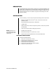
DESCRIPTION The DX3016RX Remote Viewing Software is designed for use with Microsoft Windows® 98, Windows 2000, and Windows Me. In combination with the DX3016 Series Digital Video Recorder (DVR) and an Ethernet LAN (local area network), the software can acquire live and recorded images from the DVR. The software can play back recorded images even while the DVR is recording.
NETWORK CONNECTION To connect the computer to one or more DVRs, you must use a dedicated local area network (LAN). A dedicated LAN consists of the computer and DVRs only. The following setup procedure is for Windows 98. Details may vary slightly for Windows 2000 or Windows Me. NOTE: IP addresses and subnet masks must be set correctly. Do not make or alter these settings if you do not have sufficient expertise on networks. The IP addresses 192.168.1.
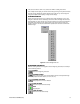
2. In the IP Address page, select Specify an IP Address and enter the IP address and subnet mask. Click OK to complete the settings and exit the menu. 00799 Figure 2. IP Address Page 3. Restart your computer. 4. Turn on the DVR(s) and set the IP address and subnet mask for each recorder. a. b. c. d. Press the SETUP button on the DVR. Select COMMUNICATION SETTING. Select TCP/IP SETTING. Set the IP address and subnet mask. 5. Connect the DVR(s) to the network through a switching hub.
OPERATION RESTRICTIONS The playback speed of the DX3016RX is determined by the computer’s processing speed, type of playback devices used, network traffic, and other factors. For these reasons, there will be cases where the software’s playback speed does not match the recording intervals of the DVR.
CONNECT TO A DVR NOTE: When the software connects to a DVR, the DVR is placed in the Lock mode. Operation of the DVR through the front panel buttons (except the camera buttons) or the RS-232C terminal is not possible while the recorder is in this mode. To connect to a DVR: 1. If the Network window is not open, click Network on the toolbar, and then click Recorder List. The Network window appears. 00801 Figure 4.
ADD A RECORDER To add a recorder to the Recorder List: 1. Click Network on the toolbar, and then click Add Recorder. The Recorder Property window appears. 00802 Figure 6. Recorder Property Window 2. Enter the DVR name and IP address in the Recorder Property window. Entering text in the Memo line is optional. 3. Click OK. DISCONNECT FROM A DVR To disconnect from a DVR: 1. Click Network on the toolbar, and then click Disconnect. 2.
If the camera number is shown in red, it means the DVR is recording that camera. In the multiple-screen display, the camera number changes from green to yellow to indicate the most recently updated field. Clicking the left mouse button on any camera image will change the multiple-camera display to a single-camera display. CUSTOM DISPLAY Clicking the right mouse button on any multiple-camera image will display a menu. Click Assign for a list of the cameras.
PLAYBACK Begins playback in the forward direction. 00798 00793 FORWARD SEARCH Starts search playback in the normal direction. Speed can be adjusted through repeated clicks of the button (1X, 2X, 4X, 8X, 1X). PLAY SPEED SLIDER Drag the slider to adjust playback speed. When set at Fast, images will be renewed at the device’s maximum speed. Slow adds roughly a three-second wait to each image shown at maximum speed. 00807 IMAGE INFORMATION In live mode, only the camera number is displayed.
ALARM SEARCH 1. Click Search on the Tool bar to open the Search menu. 2. Click Previous Alarm, Next Alarm, or Alarm List. If you click Alarm List, a list of alarms appears. Scroll through the list and click the alarm you want to view. This highlights your selection. Click the Search button. 00782 Figure 11. Alarm List Window 3. When the alarm video appears, click the Playback button. BOOKMARKS MARK A VIDEO IMAGE During video playback, you can mark video by clicking the Bookmark button.
COPY A VIDEO IMAGE This option works in both the live and playback modes. Click the Copy command in the Edit menu to copy the currently displayed image to the clipboard. PRINT A VIDEO IMAGE This option works in both the live and playback modes. 1. Click the Print command in the File menu to open the Print window. 2. Make the settings for margins, printer settings, and number of copies. Select Print the Displayed Area to print only the portion of the image visible in the window. 3.
SEQUENCE CAMERAS This option works in both the live and playback modes. To sequence all cameras: 1. 2. Click Camera in the View menu. Click All in the drop-down menu. 00786 Figure 13. Camera Selection List To sequence some cameras: 1. 2. 3. Hold down the Ctrl key on your keyboard. In the Camera box, click the buttons for the cameras that you want to sequence. Release the Ctrl key.
ZOOM This option works in both the live and playback modes. There are two ways to zoom. QUICK ZOOM TIP: Click the right mouse button anywhere within the video image to open the Shortcuts menu. Click Zoom and then click the option in the drop-down menu. The Fit to the Window option restores the original size. 1. Click Quick Zoom in the View menu. A Quick Zoom window opens. 00800 Figure 15. Quick Zoom Window 2.
TROUBLESHOOTING Refer to the following procedures if problems occur during network connection. Pelco Manual C689M (5/01) 1. Confirm that the cable is physically connected. If a switching hub is used, check that the connection has not been made to the hub’s cascade port. Recent connectors feature a guard that makes it difficult to insert the connector all the way into the recorder; check to see that the connector is all the way in. 2. Check the IP addresses and the subnet masks of the PC and the DVR(s).
PRODUCT WARRANTY AND RETURN INFORMATION WARRANTY Pelco will repair or replace, without charge, any merchandise proved defective in material or workmanship for a period of one year after the date of shipment. Exceptions to this warranty are as noted below: • Five years on FT/FR8000 Series fiber optic products. • Three years on Genex ® Series products (multiplexers, server, and keyboard).