
DVR User Manual


20 C2629M-A (6/07)
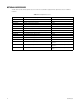
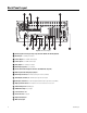
Back Panel Layout
IN1 IN2 IN3 IN4 IN5 IN6 IN7 IN8 IN9 IN10 IN11 IN12 IN13 IN14 IN15 IN16
OUT16OUT15OUT14OUT13OUT12OUT11OUT10OUT9OUT8OUT7OUT6OUT5OUT4OUT3OUT2OUT1
ALARM INPUTS RELAY OUTPUTS
1 2245678GND
9 10111213141516
1 2245678GND
9 10111213141516
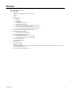
Figure 8. Back Panel Layout
ì Autoranging AC Power Input (voltage range between 100 VAC and 240 VAC, 50/60 Hz)
î Alarm Inputs: 16 normally closed inputs
ï Camera Outputs: 8 or 16 BNC camera outputs
ñ Camera Inputs: 8 or 16 BNC camera inputs
ó Relay Outputs: 16 normally open outputs
r Audio Inputs (optional): 8 or 16 channels
s Four RJ-45 Extended Peripheral Connectors (RS-422/RS-485 compliant)
t BNC Programmable Analog Display Output
u Audio Input (Standard): One miniature phone jack for line in (disabled)
~í Audio Output (Standard): One miniature phone jack for audio output
~â=Audio Input (Standard): One 2-channel (right/left) miniature phone jack for line in (disabled)
~ä High-Speed USB 2.0 Ports: two USB ports on front of unit and four on rear of unit
~ã Ethernet Adapter Port: 100 Mbps port
~å VGA Monitor Output: 15-pin output
~ç 9-Pin Serial Port: COM1
~é LPT1 Printer Port: 25-pin port
~è Keyboard (PS/2) Input
~ê Mouse (PS/2) Input