INSTALLATION MANUAL ® DX9000 Digital Video Recorder & Viewstation C662M-E (5/03)
CONTENTS Section Page IMPORTANT SAFEGUARDS AND WARNINGS .................................................................................................................................................................. 7 DESCRIPTION ..................................................................................................................................................................................................................... 8 MODELS ......................................................
DVR MANAGEMENT ................................................................................................................................................................................................ 76 DATA TRANSLATOR CONNECTIONS .............................................................................................................................................................. 76 CONFIGURING THE DATA TRANSLATOR ...............................................................................
LIST OF ILLUSTRATIONS Figure 1 2 3 4 5 6 7 8 9 10 11 12 13 14 15 16 17 18 19 20 21 22 23 24 25 26 27 28 29 30 31 32 33 34 35 36 37 38 39 40 41 42 43 44 45 46 47 48 49 50 51 52 53 54 55 56 57 58 4 Page DX9000 System Overview ................................................................................................................................................................................ 8 Recorder/Viewstation Rack-Mount Installation ...............................................................
9 60 61 62 63 64 65 66 67 68 69 70 71 72 73 74 75 76 77 78 79 80 81 82 83 84 85 86 87 88 89 90 91 92 93 94 95 96 97 98 99 100 101 102 103 104 105 User Manager Dialog Box ............................................................................................................................................................................... 55 Hardware Connection 1 ...........................................................................................................................................
LIST OF TABLES Table A B C D E F G H I J K L 6 Page Initialization Options ....................................................................................................................................................................................... 32 Security Levels ................................................................................................................................................................................................ 41 Channel Setup ......................
IMPORTANT SAFEGUARDS AND WARNINGS Prior to installation and use of this product, the following WARNINGS should be observed. 1. Installation and servicing should be done only by qualified service personnel and conform to all local codes. 2. Unless the unit is marked specifically as a NEMA Type 3, 3R, 3S, 4, 4X, 6, or 6P enclosure, it is designed for indoor use only and it must not be installed where exposed to rain and moisture. 3.
DESCRIPTION The DX9000 system consists of at least one digital video recorder (DVR), one viewstation, and one storage unit. The DX9000 digital video recorder can record images simultaneously from as many as 40 cameras at 15 images per second (ips) or from as many as 24 cameras at 30 ips. There are two types of recorders. One is compatible with DX9000HDDS storage units and one is compatible with DX9200HDDI storage units.
MODELS C662M-E (5/03) DX9000VS-C Viewstation DX9008F-C DX9016F-C DX9024F-C DX9008H-C DX9016H-C DX9024H-C DX9032H-C DX9040H-C 8-channel recorder, 30 ips per camera, Revision C software, compatible with DX9000HDDS 16-channel recorder, 30 ips per camera, Revision C software, compatible with DX9000HDDS 24-channel recorder, 30 ips per camera, Revision C software, compatible with DX9000HDDS 8-channel recorder, 15 ips per camera, Revision C software, compatible with DX9000HDDS 16-channel recorder, 15 ips per
INSTALLATION Make sure all parts are present for each unit. Recorder 1 2 2 2 2 2 4 1 2 1 4 1 1 1 Recorder Power cords (1 USA standard and 1 European standard) Brackets 6 Screws, 8-32 x .250-inch, pan head Rack ears 4 Screws, 10-32 x .250-inch, flat head 4 Screws, 10-32 x .750-inch, Phillips, pan head with washers Rear mounting rails 8 Screws, 10-32 x .375-inch, flat head Front mounting rails 6 Screws, 8-32 x .375-inch, pan head with washers Screws, 10-32 x .
INSTALLATION GUIDELINES You must adhere to the following guidelines for optimum system performance. • The DX9000 recorders and storage units require connection to an Uninterruptible Power Supply (UPS) to ensure no corruption of data during a power loss. • The DX9000 system must be installed in a climate-controlled room. The temperature range should be 41˚ to 85˚F (5˚ to 29˚C). • All network devices that will transport DX9000 video must be capable of moving multicast traffic.
MOUNTING The recorder and viewstation are supplied with the necessary parts for mounting into an industry standard 19-inch (48.26 cm) wide equipment rack. The recorder should be connected to an uninterruptible power supply (UPS) capable of supplying 2 A for 120 VAC power systems or 1 A for 230 VAC power systems. CAUTION: The units should be installed in an air-conditioned room where the temperature is maintained between 41° and 86°F (5° and 29°C).
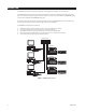
CONNECTIONS The steps and Figures 3 and 4 show how to connect the units to each other and to a network. A dedicated LAN of four or more viewstations requires a minimum network of 100BaseT (100 Mbit/sec). Integration within an existing LAN/WAN requires a network of 100BaseT (100 Mbit/sec). C662M-E (5/03) 1. Connect the viewstation to the recorder via an Ethernet switch. Use shielded network cables. 2. Connect a monitor, keyboard, and mouse to the viewstation. 3.
VIEWSTATION POWER CONNECTION 100BASET ETHERNET INTERFACE: ALLOWS MULTIPLE VIEWSTATIONS AND RECORDERS RJ-45 STRAIGHT CABLES RECORDER FOR USE BY SERVICE PERSONNEL ONLY POWER CONNECTION 37-PIN CONNECTOR SCSI CABLE 8 COAXIAL CABLES WITH BNC CONNECTORS PATCH PANEL 1 5 9 13 17 21 25 29 33 37 2 6 10 14 18 22 26 30 34 38 3 7 11 15 19 23 27 31 35 39 4 5 12 16 20 24 28 32 36 40 MINIMUM 8 CAMERA INPUTS MAXIMUM 40 CAMERA INPUTS POWER CONNECTION NOTE: EACH COAXIAL CABLE HAS A NUMB
VIEWSTATION POWER CONNECTION 100BASET ETHERNET INTERFACE: ALLOWS MULTIPLE VIEWSTATIONS AND RECORDERS RJ-45 STRAIGHT CABLES RECORDER (IDE COMPATIBLE) FOR USE BY SERVICE PERSONNEL ONLY POWER CONNECTION 37-PIN CONNECTOR SCSI CABLE 8 COAXIAL CABLES WITH BNC CONNECTORS PATCH PANEL 1 5 9 13 17 21 25 29 33 37 2 6 10 14 18 22 26 30 34 38 3 7 11 15 19 23 27 31 35 39 4 5 12 16 20 24 28 32 36 40 NOTE: EACH COAXIAL CABLE HAS A NUMBER (1-8).
PROGRAMMING You must use pcAnywhere to access a DX9000 recorder and configure it. You can find a shortcut to the pcAnywhere application on your viewstation desktop. RECORDER NETWORK CONFIGURATION After you make all connections, you have to configure the network on the recorder. To configure the recorder, you need the following information. You can obtain this information from your network administrator. • Unique recorder name: (Examples are Pelco1, Pelco2, Pelco3, etc. This is the default naming scheme.
4. Click Properties. Figure 6. Recorder Identification Changes Dialog Box 5. 6. 7. Enter the new computer name or workgroup. Click OK. Reboot. It takes about five minutes for the recorder to reboot. If you cannot wait that long, then wait two minutes, open the recorder door, and turn the power off and back on.
CHANGING THE RECORDER’S IP ADDRESS To change the recorder’s IP address: 1. Close all windows on the recorder desktop. 2. Right-click My Network Places and go to Properties. Figure 7.
3. Double-click Local Area Connection. Figure 8. Recorder Local Area Connection Status Dialog Box 4. Click Properties. Figure 9. Recorder Local Area Connection Properties Dialog Box 5. C662M-E (5/03) Make sure the “Show icon in taskbar when connected” checkbox is selected.
6. Double-click Internet Protocol (TCP/IP). Figure 10. Recorder Internet Protocol (TCP/IP) Properties Dialog Box 7. Enter the IP address (For example, 100.0.0.101). The last three digits must be different for each recorder (For example, 101, 102, 103, etc.). 8. Enter the Subnet mask. NOTE: You may also have to enter your default gateway address and your DNS server address(es). 9. Click OK. NOTE: After changing the recorder’s IP address, you must go to the Server Configuration Utility.
VIEWSTATION NETWORK CONFIGURATION After you make all connections, you also have to configure the network on the viewstation. To configure the viewstation, you need the following information. You can obtain this information from your network administrator. • Unique viewstation name: (Examples are Pelcovs1, Pelcovs2, Pelcovs3, etc. This is the default naming scheme.) • Unique IP address: (Examples are 100.0.0.201, 100.0.0.202, 100.0.0.203, etc. This is the default addressing scheme.
Figure 12. Viewstation Identification Changes Dialog Box 5. 6. 7. 22 Enter the new computer name or workgroup. Click OK. Reboot.
CHANGING THE VIEWSTATION’S IP ADDRESS To change the viewstation’s IP address: 1. Close all windows on the viewstation desktop. 2. Right-click My Network Places and go to Properties. Figure 13. Viewstation Network Connections Window 3. C662M-E (5/03) Double-click Local Area Connection.
Figure 14. Viewstation Local Area Connection Status Dialog Box 4. Click Properties. Figure 15. Viewstation Local Area Connection Properties Dialog Box 5. 24 Make sure the “Show icon in taskbar when connected” checkbox is selected.
6. Double-click Internet Protocol (TCP/IP). Figure 16. Viewstation Internet Protocol (TCP/IP) Properties Dialog Box 7. Enter the IP address (For example, 100.0.0.201). The last three digits must be different for each viewstation (For example, 201, 202, 203, etc.). 8. Enter the Subnet mask. NOTE: You may also have to enter your default gateway address and your DNS server address(es). 9. C662M-E (5/03) Click OK.
CLIENT CONFIGURATION UTILITY You can use this utility to build a list of local servers and to synchronize the time between recorders and viewstations. 1. Go to Start > Programs > DX9000 Viewstation > Client Configuration Utility. Figure 17. Client Configuration Login Dialog Box 2. Enter admin in the “User name” field and admin in the “Password” field. 3. Click Login. Figure 18. Client Configuration Utility 4. Select “Build a list of local servers.” 5. Select “Standard naming” or “Custom naming.
Figure 19. Verify Settings Dialog Box 7. Click Yes. Figure 20. Operation Complete Dialog Box 8. Click OK. Figure 21. Client Configuration Success Dialog Box 9. C662M-E (5/03) Click Close.
TIME SYNCHRONIZATION All equipment in your system must have the same time. Pelco recommends you select all recorders as time synchronization recorders. Creating this chain ensures that the system will maintain the correct time in case one or more recorder fails. All recorders and viewstations must belong to the same workgroup or local area network (LAN). Follow these steps for each viewstation: 1. 2. Make sure that each viewstation is connected to the network switch.
Figure 23. Edit Time Zone Dialog Box 4. 5. 6. 7. Verify that the “Automatically set Daylight Saving Time” checkbox is selected, if applicable for the location of installation. Click OK. Close the Windows® NT Time Zone Editor. Click Configure. Figure 24. Verify Settings Dialog Box 8. Click Yes. Figure 25. Operation Complete Dialog Box 9. C662M-E (5/03) Click OK.
10. Select the “Export to server” radio button. Figure 26. Export to Server Dialog Box 11. Select the name of the first recorder from the drop-down box. 12. Click Configure. Figure 27. Verify Settings Dialog Box 13. Click Yes. Figure 28. Operation Complete Dialog Box 14. Click OK. NOTE: You must follow these steps for each recorder that is in the drop-down box. Refer to the Server Configuration Utility section to complete time synchronization.
SERVER CONFIGURATION UTILITY Windows should boot up to the desktop without user intervention. Make sure all applications on the recorder are closed. 1. Go to Start > Programs > DX9000 Server > DX9000 Server Configuration Utility. Figure 29. Server Configuration Utility Dialog Box Table A describes the Initialization Options. These options are preconfigured. The only checkbox you should select is “Define time synchronization chain.
Table A. Initialization Options Option Description Initialize New Channels The number of channels for the recorder is displayed. Half or Full frame rate is selected. The Quarter frame rate setting is reserved for future development. Recording Format The recording format is set for your location: PAL or NTSC. Resolution CIF resolution is selected. The 2CIF resolution setting is reserved for future development. Multicast Group 239 is displayed in the first text box.
Figure 31. Edit Time Zone Dialog Box 5. 6. 7. 8. Verify that the “Automatically set Daylight Saving Time” checkbox is selected, if applicable for the location of installation. Click OK. Close the Windows NT Time Zone Editor. Click Configure. Figure 32. Verify Settings Dialog Box 9. Click Yes. Figure 33. Operation Complete Dialog Box 10. 11. 12. 13. C662M-E (5/03) Click OK. Select the “Define time synchronization chain” checkbox from the Server Configuration Utility dialog box. Click Suggest.
MYLEX ALERT MANAGER NOTE: The Mylex Alert Manager is not available on the IDE-compatible recorders. The Mylex Alert Manager sends an alert to DX9000 viewstations whenever there is a problem. The Workstation Array Manager application should be running in the background all the time. For example, if a hard disk drive storage unit fails, the application appears onscreen. To create a server alert file: 1. Click My Computer from your desktop. 2. Click Local Disk (C:). 3. Click Program Files. 4.
Figure 35. New Text Document Window 8. C662M-E (5/03) Double-click the file. Notepad opens.
9. Enter the name of the DX9000 viewstation you want to alert and then enter the event message text. Follow the example below. Figure 36. Example Event Message Text Window NOTE: Duplicate the line if you want to alert more than one viewstation. Remember to specify the viewstation names. 10. Save your changes and close Notepad. 11. Go to Tools > Folder Options > View.
Figure 37. Folder Options Page 12. Uncheck “Hide file extensions for known file types.” 13. Click Apply and then OK. 14. Rename Server Alert.txt to Server Alert.bat. Figure 38. Rename File Dialog Box 15. Click Yes.
Figure 39.
To set the settings for events: 1. Go to Start > Programs > Startup > Mylex Workstation Array Manager 3.01. Figure 40. Workstation Array Manager Window 2. C662M-E (5/03) Click .
Figure 41. Alert Preferences Page 3. 4. 40 Make sure “Append to log file” and “Enable event logging” are selected. Select the event security level(s) in the Launch Application section. Refer to Table B.
Table B. Security Levels C662M-E (5/03) Priority Event Definition Example 0 Critical Controller is dead. System is disconnecting from this controller. Controller is gone. System is disconnecting from this controller. Bad blocks found. Controller is using default non-unique world-wide name. Mirror race on critical drive. 1 Serious A hard disk has failed. Physical drive missing on startup. Fan failure. Over temperature. Power supply failure. Uninterruptible power supply failed.
5. Click the Alarm Setup tab. Figure 42. Alarm Setup Page 6. Select Launch Application and then click Add. Figure 43. Launch Application Dialog Box 7. 8. 42 Make sure the “Enabled” checkbox is selected and the “Launch Only Once” checkbox is not selected. Click Browse.
Figure 44. Select Batch File Dialog Box 9. Select Server Alert.bat and then click Open. Figure 45.
10. Click Test. The message below appears on the recorder and Messenger Service opens on the viewstation. Figure 46. Application Test Window Figure 47. Messenger Service Dialog Box 11. Click OK. Figure 48. Successful Test Page 12. Click OK.
SETTING UP THE SYSTEM System administrators and operators with a Level 1 authorization can set camera recording properties. However, only system administrators can define user names and passwords for the DX9000 viewstation. To open the DX9000 viewstation application, double-click the desktop icon and log in. CAMERA RECORDING PROPERTIES 1. Click System > Properties on the main toolbar. Figure 49. Camera Properties Dialog Box 2. C662M-E (5/03) Click “Select channel” to display a list of recorders.
Figure 50. Select Channel Dialog Box 3. 46 Select a channel.
Figure 51. Continuous Recording Schedule Page 4. C662M-E (5/03) Select the “Preview” checkbox to verify that you have the correct camera.
Continuous Recording Schedule 1. Select the “Continuous recording” radio button. (This is the default setting and should be selected already when you select a channel.) 2. Click Apply. Recording is done at all times and no schedule is defined. The entire daily and weekly recording schedules are marked in light yellow, and any previous definitions on the schedules are removed.
Daily Recording Schedule 1. 2. Select the “Daily recording schedule” radio button. Click in the time bar the desired starting time for recording or enter the exact start/end times in the “Fine tune” fields. The example below shows continuous daily recording from 7:05 A.M. to 12:05 P.M. The box in the time bar is blue with a red border. You can make the box smaller or larger by dragging it using your mouse. Figure 52.
If you select event recording, the DX9000 actually records continuously. The difference between continuous and event recording is the way the video is saved to the database. When the hard drives are full, the DX9000 starts overwriting the oldest video. With continuous recording, the DX9000 overwrites the video in the order in which it was recorded, whether it is an event or a non-event. With event recording, the DX9000 overwrites non-events first and then events. Data is overwritten on a day-by-day basis.
Weekly Recording Schedule 1. Select the “Weekly recording schedule” radio button. 2. Click in the time bars the desired starting time for recording for each day of the week or enter the exact start/end times in the “Fine tune” fields. The example below shows continuous weekly recording from 7:05 A.M. to 12:05 P.M. The boxes in the time bars are blue with a red border. You can make the boxes smaller or larger by dragging them using your mouse. Figure 54.
Motion Detection 1. Click the DVMD tab. Figure 56. Motion Detection Page 52 2. Select the “Detector on” radio button. 3. Select the “Preview” checkbox. The video has blue squares over the entire area meaning the entire video has been selected for motion detection. 4. Click “Clear all” to remove all of the boxes or click the right mouse button on each box you want to remove. To undo your changes, click “Discard changes.” Click “Mark all” to select the entire video for motion detection. 5.
Channel Setup This section describes how to set camera properties to get the best picture. 1. Click the Video tab. Figure 57. Camera Video Setup Page 2. 3. 4. Select the “Preview” checkbox to see the video quality with the default settings. Adjust the video quality. Click Apply. NOTE: The bit rate, located under the “Select channel” button, displays the amount of activity in the specified channel. A higher bit rate requires more storage space.
Table C. Channel Setup Parameter 54 Description/Action Channel Name Enter a new name for this channel. You can enter up to 20 characters. Brightness Drag the triangle to change the brightness value. The higher the value, the higher the bit rate. The previous value is displayed to the right of the brightness bar. Contrast Drag the triangle to change the contrast value. The higher the value, the higher the bit rate. The previous value is displayed to the right of the contrast bar.
DEFINING USERS This option is for system administrators only. Other users trying to access this option will get the following message: Figure 58. User Access Dialog Box This option allows an administrator to add, delete, and change the properties of users in the DX9000 system. There are seven predefined user access levels ranging from Administrator to Operator Level 6. Each user is assigned different access rights to the DX9000 network and videos. Click System > Users on the main toolbar.
Table D. User Access Rights User Live Video/ Live Events Video Locked Playback/ Video Query/Sherlock Playback Lock Video Export Image/ Video Unlock Video/ Define Change Camera Users/Audit Settings Viewer Administrator ✓ ✓ ✓ ✓ ✓ ✓ Operator Level 1 ✓ ✓ ✓ ✓ ✓ ✓ Operator Level 2 ✓ ✓ ✓ ✓ ✓ Operator Level 3 ✓ ✓ ✓ ✓ Operator Level 4 ✓ ✓ ✓ Operator Level 5 ✓ ✓ Operator Level 6 ✓ ✓ Edit Existing Users 1. Select the server name from the “Filter per server” drop-down box.
ADVANCED PROGRAMMING I/O INTEGRATION The DX9000 system can interface to the CM9760 matrix. It can integrate with the CM9760-DT, CM9760-ALM, and CM9760-REL. You can configure the I/O (input/output) integration feature to send and receive events to the external devices. The CM9760-DT data translator translates the ASCII protocol to the P protocol of the CM9760 matrix switch. The CM9760-ALM alarm unit is an input device with 64 ports. You can connect up to four alarm units to each DX9000 recorder.
HARDWARE CONNECTIONS The I/O configuration allows creating several different connections between the recorder and the external devices. See the example figures below. RECORDER #4 RECORDER #3 RECORDER #5 ALARM UNIT RELAY UNIT ALARM UNIT RELAY UNIT ALARM UNIT RELAY UNIT ALARM UNIT RELAY UNIT ETHERNET RS-232 RS-232 TO RS-422 CONVERTER RECORDER #2 RECORDER #1 Figure 60.
Connecting an Alarm Unit To connect a CM9760-ALM to a DX9000 recorder using RS-232 communication: 1. Connect a null modem cable from the alarm unit’s RS-232 port to the COM 1 or COM 2 port on the recorder. 2. Set the DIP Switches on the alarm unit for RS-232 communication. Refer to the CM9760-ALM Installation/Operation manual. If using RS-422 communication: 1. Connect a cable from the alarm unit’s RJ-45 COM IN port to the COM 1 or COM 2 port on the recorder via an RS-232 to RS-422 converter. 2.
Connecting a Relay Unit To connect a CM9760-REL to a DX9000 recorder: 1. Connect a cable from the relay unit’s RJ-45 COM IN port to the COM 1 or COM 2 port on the recorder via an RS-232 to RS-422 converter. 2. Set the DIP Switches on the relay unit for RS-422 communication. Refer to the CM9760-REL Installation/Operation manual. DX9008F-C USE EITHER COM 1 OR COM 2 RS-232 TO RS-422 CONVERTER CM9760-REL Figure 64.
Connecting a Data Translator To connect a CM9760-DT to a DX9000 recorder: 1. 2. 3. Connect a null modem cable from the CM9760-DT’s COM A port to the COM 1 or COM 2 port on the recorder. Connect a null modem cable from the CM9760-DT’s COM B port to COM 1 or COM 2 port on the CM9760-CC1. Set the jumpers in the data translator for baud rate and parity. Refer to the CM9760-DT Installation/Operation manual. NOTE: You can also connect the CM9760-DT to one of the CM9760-CC1 SERCOM ports for RS-422 communication.
I/O HANDLER CONFIGURATION ALARM UNIT INTEGRATION The following steps show how to configure an alarm unit. This programming is required only on the recorder that is physically connected to the CM9760-ALM. 1. Go to Start > Programs > DX9000 Server > I/O Handler Configuration. Figure 66. Alarm I/O Handler Configuration 2. Click Select Driver to define the external device driver that is connected to the server. Figure 67. CM9760 Alarm Driver 3. 4. Select CM9760ALM.dll. Click Open. Figure 68.
Figure 69. CM9760 Alarm Configuration Table E. Alarm Configuration 6. 7. 8. 9. C662M-E (5/03) Term Definition Baud Rate Set according to the external alarm device settings. COM Port The COM port on the recorder that the alarm unit is connected to. Event Type Not used. Set with default value 4. Event Category Not used. Set with default value 0. Default Interval The time interval between two events. This sets the same interval for the entire alarm ports.
RELAY UNIT INTEGRATION The following steps show how to configure a relay unit. This programming is required only on the recorder that is physically connected to the CM9760-REL. 1. Go to Start > Programs > DX9000 Server > I/O Handler Configuration. Figure 70. Relay I/O Handler 2. Click Select Driver to define the external device driver that is connected to the server. Figure 71. CM9760 Relay Driver 3. 4. Select CM9760REL.dll. Click Open. Figure 72. Device 1 Relay Driver 5. 64 Click Configure.
Figure 73. CM9760 Relay Configuration Table F. Relay Configuration 6. 7. 8. 9. C662M-E (5/03) Term Definition Baud Rate Set according to the external relay device settings. Parity Set according to the external relay device settings. COM Port The COM port on the recorder that the relay unit is connected to. Frame Address Not used. Set with default value 0. Default Latch Time The relay latch time that activates the relays on the relay unit.
DATA TRANSLATOR INTEGRATION The following steps show how to configure a data translator unit. This programming is required only on the recorder that is physically connected to the CM9760-DT. 1. Go to Start > Programs > DX9000 Server > I/O Handler Configuration. Figure 74. Data Translator I/O Handler Configuration 2. Click Select Driver to define the external device driver that is connected to the server. Figure 75. CM9760 Data Translator Driver 3. 4. Select CM9760DT.dll. Click Open. Figure 76.
Figure 77. CM9760 Relay Configuration Table G. Data Translator Configuration Term 6. 7. 8. 9. C662M-E (5/03) Definition Baud Rate Set according to the external data translator device settings. Parity Set according to the external data translator device settings. COM Port The COM port on the recorder that the data translator is connected to. Time Synch Update The interval that the recorder updates the CM9760 clock. The default is 21600 seconds (6 hours).
I/O MANAGER CONFIGURATION ALARM UNIT CONFIGURATION The following steps show how to configure an alarm unit that is installed in the I/O Handler. 1. Go to Start > Programs > DX9000 Server > I/O Manager Configuration. Figure 78. I/O Manager Configuration – Overview 2. Click Next. Figure 79.
Table H. External 1 Source Term 3. 4. 5. 6. Definition Server The server name that the alarm unit is connected to. Port The port number on the alarm unit that relates to a specific channel. If several channels are selected, this number specifies the related port of the first channel. For example, if 8 channels are selected, port 0 relates to channel 0 and so on. Device The logical device number that the alarm unit is connected to and configured on the I/O Handler. OK Confirm the configuration.
Figure 81. External 1 8. Click Next. Figure 82. Configure External 2 Source 9. Follow the previous steps if you want to define a second event. 10. Click Next.
Figure 83. Configure Event Destination 11. Click Next. Figure 84. Configure Output Events 12. Click Finish.
RELAY UNIT CONFIGURATION The Step 3 and Step 4 screens in the I/O Manager Configuration are used to configure a relay unit. Step 3 configures the recorder channels with the selected relay ports. Step 4 translates the event type from one type to another, if necessary. Figure 85. Relay Unit Step 3 Screen Table I. Relay Unit Event Destination 1. 2. 3. 4. Term Definition Server The server name that the relay unit is connected to.
5. Click OK and then Next. Figure 86. Relay Unit Step 4 Screen 6. Select the event type to translate. NOTE: Do not select “Stop Recording” and “Start Recording.” They are reserved for future use. 7. 8. C662M-E (5/03) Select “No translation.” You must always select this. Click OK and then Finish.
DATA TRANSLATOR CONFIGURATION The Step 3 and Step 4 screens in the I/O Manager Configuration are used to configure the data translator. Step 3 configures the recorder channels with the selected data translator. Step 4 translates the event type from one type to another, if necessary. Figure 87. Data Translator Step 3 Screen Table J. Data Translator Event Destination 74 Term Definition Server The server name that the data translator is connected to.
1. 2. 3. 4. Select the channel(s) you want to configure with the data translator. Enter the server name that the data translator is connected to. Select the device number as configured in the I/O Handler. In the port field, enter the alarm number you want to activate in the matrix. NOTE: In the port field, you can enter and configure only alarm numbers (physical and logical numbers in the CM9760 System Manager). If you select several channels, the port number you enter will be the starting port.
DVR MANAGEMENT The Server Alert Configuration Utility can be used to send events to the CM9760-DT data translator or the CM9760-REL relay unit. The server state sends a string to the data translator. The string is different for each recorder so the matrix recognizes which recorder has the problem. The server state activates the relay unit. The server state is configured to activate a specific relay port in case of a problem.
CONFIGURING THE DATA TRANSLATOR 1. Go to Start > Programs > DX9000 Viewstation > Server Alert Configuration Utility. Figure 90. Data Translator Configuration 2. Enter the offset number in the Server Alert Settings box. NOTE: The offset number must match the logical and physical numbers of the first alarm in the CM9760 System Manager. 3. Click Select. Figure 91. Data Translator Driver 4. 5. Select CM9760DT.dll. Click Open. Figure 92.
6. Click Configure. Figure 93. CM9760-DT Configuration Table K. CM9760-DT Settings Term Definition Baud Rate Set the baud rate according to the data translator settings. Parity Set the parity according to the data translator settings. COM Port This is the COM port on the viewstation that the data translator is connected to. 7. 8. 9. 10. Set the baud rate to 4800 and the parity to Even. Enter the COM port that the data translator is connected to on the viewstation. Click OK. Click Test.
RELAY UNIT CONNECTIONS You can connect 1 to 4 relay units to each viewstation. The CM9760-REL should be used with third party matrix switcher for hard-wired alarm integration. 1. Connect a cable from the relay unit’s RJ-45 COM IN port to the COM 1 or COM 2 port on the viewstation via an RS-232 to RS-422 converter. 2. Set the DIP switches on the relay unit for RS-422 communication. Refer to the CM9760-REL Installation/Operation manual.
CONFIGURING THE RELAY UNIT 1. Go to Start > Programs > DX9000 Viewstation > Server Alert Configuration Utility. Figure 95. Relay Unit Configuration 2. 3. Enter the logical relay number in the Server Alert Settings box. Click Select. Figure 96. Relay Unit Driver 4. 5. Select CM9760REL.dll. Click Open. Figure 97. Relay Unit Driver Settings 6. 80 Click Configure.
Figure 98. CM9760-REL Configuration Table L. CM9760-REL Settings Term Baud Rate Set the baud rate according to the External Relay device settings. Parity Set the parity according to the External Relay device settings. COM Port This is the COM port on the viewstation that the relay unit is connected to. Frame Address This should be set with the default values of 0. Default Latch Time (sec) The minimum time that is detected by the relay unit. This sets the latch time for all the relay ports.
FOREIGN LANGUAGE You can select only the following locations for use with the DX9000 system: • • • • • English (United States) French (France) German (Germany) Portuguese (Brazil) Spanish (Spain) In the example below, the location is changed from English (United States) to Spanish (Spain). 1. Double-click My Computer. Figure 99. My Computer 2. 82 Double-click Control Panel.
Figure 100. Control Panel 3. Double-click Regional Options. Figure 101.
4. Change the location to Spanish (Spain). Figure 102. Change System Location 5. 6. Click Apply. Click Set Default. Figure 103. Select System Location 7. 8. 9. 84 Select the same location. Click OK. Click Apply.
Figure 104. General Dialog Box 10. Click Yes. Figure 105. Restart Computer Dialog Box 11. Click Yes. The new settings take affect after the computer reboots. The DX9000 will support Spanish settings for numbers, currency, times, dates, menu strings, and text translations. Follow these same steps to change the location back to English (United States) or to select another location. NOTE: English (United States) is the default location.
TROUBLESHOOTING If you encounter a minor problem with your computer, monitor, or software, refer to the following list of general suggestions before taking further action: • • • • • • • • 86 If you cannot log in to the system, check your user name and password. Make sure the computer and monitor are plugged into a working electrical outlet. Make sure the computer’s green power light is on. Make sure the monitor’s green light is on. If the monitor is dim, adjust the brightness and contrast controls.
SPECIFICATIONS RECORDER Electrical/Video Input Voltage: Power Consumption: Signal System: Operating System: Recording Resolution NTSC: PAL: Compression: Compressed Image Size: Video Inputs: 100-240 VAC, 50/60 Hz, autoranging 195 W maximum NTSC/PAL Windows 2000 and SP2 Service Pack Video Outputs: Remote Control: 352 x 240 pixels 352 x 288 pixels MPEG 352 x 240: average 1.
REGULATORY NOTICES This equipment has been tested and found to comply with the limits of a Class A digital device, pursuant to part 15 of the FCC rules. These limits are designed to provide reasonable protection against harmful interference when the equipment is operated in a commercial environment. This equipment generates, uses, and can radiate radio frequency energy and, if not installed and used in accordance with the instruction manual, may cause harmful interference to radio communications.
WARRANTY AND RETURN INFORMATION WARRANTY Pelco will repair or replace, without charge, any merchandise proved defective in material or workmanship for a period of one year after the date of shipment. Exceptions to this warranty are as noted below: • Five years on Pelco manufactured cameras (CC3500/CC3600/CC3700 and MC3500/MC3600 Series); two years on all other cameras. • Three years on Genex® Series (multiplexers, server, and keyboard) and 090 Series Camclosure® Camera System.
® World Headquarters 3500 Pelco Way Clovis, California 93612 USA USA & Canada Tel: 800/289-9100 Fax: 800/289-9150 International Tel: 1-559/292-1981 Fax: 1-559/348-1120 www.pelco.