® EH5700 Series Environmental Enclosure Installation/ Operation Manual C1431M-C (8/04) Pelco • 3500 Pelco Way, Clovis • CA 93612-5699 USA • www.pelco.
CONTENTS Section Page GENERAL ................................................................................................... 3 IMPORTANT SAFEGUARDS AND WARNINGS ............................................... 3 DESCRIPTION .................................................................................................. 4 MODELS ................................................................................................... 4 INSTALLATION ...........................................................
GENERAL IMPORTANT SAFEGUARDS AND WARNINGS Prior to installation and use of this product, the following WARNINGS should be observed. 1. Installation and servicing should only be done by Qualified Service Personnel and conform to all Local codes. 2. Unless the unit is specifically marked as a NEMA Type 3, 3R, 3S, 4, 4X, 6, or 6P enclosure, it is designed for indoor use only and it must not be installed where exposed to rain and moisture. 3. Only use replacement parts recommended by Pelco. 4.
DESCRIPTION Environmental enclosures in the EH5700 Series are used with Pelco’s pan/tilt units or fixed mounts. The enclosures are constructed of aluminum. You can install cameras with either fixed focal length lenses or motorized zoom lenses. All models have an adjustable camera sled to accommodate different sizes of cameras and lenses. MODELS 4 EH5723 Environmental enclosure with rear-opening lid. Lid has gas spring to hold it open. 23-inch (58.42 cm) length.
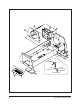
INSTALLATION 1. Unlatch and raise the enclosure lid. The gas spring will hold the lid in place when it is fully opened. 2. Remove the camera sled from the rail: 3. a. Loosen the screws. b. Slide the sled so that the screws are in the large part of the mounting slots. c. Remove the sled. d. Remove the parts tied to the sled.
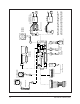
C 4 D 5 B C A B 3 B A TO FAN BLACK 22 GA. (1 FT.) RED 22 GA. (1 FT.) TO PC BOARD 2 24 VAC MODELS 1 Figure 1.
. Install the sled and camera/lens in the enclosure: a. If the camera’s lens is adjustable, extend the lens to its maximum length. b. Place the sled over the mounting screws in the enclosure. c. Slide the sled forward until the camera’s lens almost touches the window. d. Tighten the screws to secure the camera sled to the enclosure. 8. Wire the video output from the camera. 9. If you are going to synchronize cameras, wire the camera’s synchronization connection. 10.
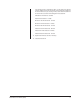
WARNING: Camera damage possible. You can damage your camera if you connect it to the wrong connector. When the power requirements are the same, there are two ways to connect power: (1) If your camera will use the same power as the enclosure, plug the camera into the CAM 1 socket on the circuit board. If your camera’s voltage will be different from the enclosure’s voltage, plug the camera into the CAM 2 socket. DO NOT plug the camera into the CAM 1 socket or you can damage your camera.
If the camera’s power is connected to CAM 1 on the circuit board, add the camera’s wattage to the power consumption of the accessories to determine the size of wire to use. If you are using 24 VAC, refer to Table A to determine the size of wire to use.
Figure 2. EH5700 Series Input Wiring Diagram RED BLK 1 2 PLUG CPC CONN.
Table A. 24 VAC Wiring Distances The following are the recommended maximum distances for 24 VAC applications and are calculated with a 10-percent voltage drop. (10-percent is generally the maximum allowable voltage drop for AC-powered devices.) EXAMPLE: An enclosure that re- Wire Gauge Total VA 20 AWG 18 AWG 16AWG 14 AWG 12 AWG 10 AWG (0.5 mm2) (1.0 mm2) (1.5 mm2) (2.5 mm2) (4.0 mm2) (6.0 mm2) NOTE: Distances are calculated in Total vA consumed feet; values in parentheses are meters.
OPERATION If your enclosure has a thermostatically controlled blower, the thermostat is set to turn the fan on between 77° and 93°F (25° and 34°C) and to turn the fan off between 62° and 78°F (17° and 26°C). If your enclosure has thermostatically controlled heaters or defroster, the thermostat is set to turn them on between 42° and 58°F (6° and 14°C) and to turn them off between 72° and 88°F (22° and 31°C).
MAINTENANCE Perform the following maintenance at regularly scheduled intervals to prolong the operational life and appearance of the equipment. 1. Clean the window with a mild non-abrasive detergent in water and a soft cloth to maintain picture clarity. 2. If your enclosure has a blower, clean the foam filters as follows: a. On the bottom front of the enclosure, remove the two screws in the vent grill. b. Remove the vent grill and take out the filters. c.
SPECIFICATIONS ELECTRICAL Input Voltage: Electrical Connections: 24, 120 or 230 VAC, 50/60 Hz One each of the following when equipped with optional circuit board (O/I-PCB): 3-connector terminal block for power input 6-pin lens connector 9-connector terminal block for lens wiring 10-connector terminal block for camera/lens wiring 2-connector terminal block for spare connections 3-pin socket for camera power input 2-pin socket for optional camera power input 2-pin socket for blower 2-pin socket for defroste
Latches: Stainless Steel Dimensions: See Figure 3 Unit Weight EH5723: 11 lbs (4.99 kg) EH5723-1, -2, -3: 13 lbs (6.37 kg) EH5729: 16 lbs (7.26 kg) EH5729-1, -2, -3: 18 lbs (8.14 kg) Shipping 12 lbs (5.44 kg) 15 lbs (6.80 kg) 18 lbs (8.16 kg) 20 lbs (9.07 kg) GENERAL NEMA Rating: Meets NEMA 3R Standards IEC 144 Rating: IP54 (EH5700-1, -2, -3) Environment: Indoor/outdoor -10° to 120°F (-23° to 49°C) (Design and product specifications subject to change without notice.) MODEL A B C EH5723 23.
PRODUCT WARRANTY AND RETURN INFORMATION WARRANTY Pelco will repair or replace, without charge, any merchandise proved defective in material or workmanship for a period of one year after the date of shipment. Exceptions to this warranty are as noted below: • Five years on FT/FR8000 Series fiber optic products. • Three years on Genex ® Series products (multiplexers, server, and keyboard).