I N S TA L L AT I O N MANUAL ® EM3512 Feedthrough Wall Mount for EH3512 Series 24 VAC Enclosures C268M-B (8/05)
IMPORTANT SAFEGUARDS AND WARNINGS Prior to installation and use of this product, the following WARNINGS should be observed. 1. Read these instructions. 2. Keep these instructions. 3. Heed all warnings. 4. Follow all instructions. 5. Do not block any ventilation openings. Install in accordance with the manufacturer’s instructions. 6. Do not install near any heat sources such as radiators, heat registers, stoves, or other apparatus (including amplifiers) that produce heat. 7.
DESCRIPTION The EM3512 Feedthrough Wall Mount provides an attractive mount for the following EH3512 enclosures that use 24 VAC power: EH3512 enclosure when a 24 VAC camera is installed EH3512-2 enclosure EH3512-2HD enclosure Video and power wiring are pre-installed and concealed within the mount. NOTE: The EM3512 mount cannot be used with the EH3508 Series and EH3515 Series enclosures.
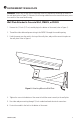
INSTALLATION The following parts are supplied: EM3512 mount 5/32-inch hex wrench Two 1/4-20 x 5/8-inch Phillips screws 24 VAC POWER WIRING FEMALE BNC CONNECTOR 24 VAC POWER WIRING SCREW HOLES TO ATTACH EH3512 TILT ADJUSTING SCREW PAN ADJUSTING SCREW MALE BNC CONNECTOR CONDUIT FITTING WALL PLATE FASTENING SCREW WALL PLATE Figure 1. EM3512 Feedthrough Wall Mount INSTALL THE WALL PLATE 1.
Table A. Minimum Hardware Requirements Mount Wall Recommended Mounting Surface Solid Concrete* Wall board/2x4’s Plywood (3/4-inch construction grade) Electrical Box Wall stud Recommended Hardware Four 1/4 x 13/4-inch strike anchors Two 1/4 x 2-inch lag bolts (bolts must be attached to stud) Four 1/4 x 2-inch lag bolts Hardware sufficient to penetrate stud 1 inch *Recommended strength of concrete is 3600 psi or 25 Mpa. Concrete Wall To mount to a concrete wall (refer to Figure 3): a.
Electrical Box To mount to an electrical box (refer to Figure 3): a. Fasten the electrical box to a wall stud with hardware recommended in Table A. b. Bring video and power wiring into the electrical box, and then through the star cutout and oblong hole in the center of the wall plate. c. Attach the wall plate to the electrical box. Make sure the wall plate is oriented properly; TOP is written on the gasket on the back of the wall plate.
FASTEN MOUNT TO WALL PLATE WARNING: Make sure the pan and tilt adjusting screws are tight before attaching the mount to the wall plate (refer to Figure 1). Otherwise, the housing could move on the mount and cause you to lose control of the mount and housing. Wall Plate Attached to Concrete Wall, CM3512, or PA3512 1. Remove the 1/2-inch (1.27 cm) conduit plug in the bottom of the mount (refer to Figure 1). 2. Thread the video cable and power wiring in the EM3512 through the conduit opening. 3.
Wall Plate Attached to Wall or Electrical Box 1. Connect the video and power wiring. 2. Hook the mount over the notch in the top of the wall plate, and push the mount into place on the wall plate. Refer to Figure 4. 3. Replace the screw in the bottom of the mount and tighten it to hold the mount securely to the wall plate. COMPLETE INSTALLATION Refer to the EH3512 Installation/Operation Manual to complete the installation.
SPECIFICATIONS MECHANICAL Pan Adjustment: Tilt Adjustment: Locking Method: 320° ±90° Socket head cap screws that require 5/32-inch hex wrench GENERAL Environment: Construction: Finish: Dimensions: Weight: C268M-B (8/05) Indoor/outdoor Aluminum Gray polyester powder coat 14.33 (L) x 3.57 (W) x 4.93 (H) inches (36.40 x 9.07 x 12.52 cm) 1.95 lb (0.
C268M-B (8/05)
WARRANTY AND RETURN INFORMATION WARRANTY Pelco will repair or replace, without charge, any merchandise proved defective in material or workmanship for a period of one year after the date of shipment. Exceptions to this warranty are as noted below: • Five years on FT/FR8000 Series fiber optic products. • Three years on Genex® Series products (multiplexers, server, and keyboard).
® World Headquarters 3500 Pelco Way Clovis, California 93612 USA USA & Canada Tel: 800/289-9100 Fax: 800/289-9150 International Tel: 1-559/292-1981 Fax: 1-559/348-1120 www.pelco.