INSTALLATION/OPERATION IXE Series Extended Platform Network Camera Sarix Technology ™ C2953M-A (5/09)
Contents Regulatory Notices . . . . . . . . . . . . . . . . . . . . . . . . . . . . . . . . . . . . . . . . . . . . . . . . . . . . . . . . . . . . . . . . . . . . . . . . . . . . . . . . . . . . . . . . . . . . . . . . . . . . 6 Video Quality Caution . . . . . . . . . . . . . . . . . . . . . . . . . . . . . . . . . . . . . . . . . . . . . . . . . . . . . . . . . . . . . . . . . . . . . . . . . . . . . . . . . . . . . . . . . . . . . . . . . . 7 Open Source Software Notice. . . . . . . . . . . . . . . . . .
Help Menu . . . . . . . . . . . . . . . . . . . . . . . . . . . . . . . . . . . . . . . . . . . . . . . . . . . . . . . . . . . . . . . . . . . . . . . . . . . . . . . . . . . . . . . . . . . . . . . . . . . . . . . . . . 54 Log Off Menu . . . . . . . . . . . . . . . . . . . . . . . . . . . . . . . . . . . . . . . . . . . . . . . . . . . . . . . . . . . . . . . . . . . . . . . . . . . . . . . . . . . . . . . . . . . . . . . . . . . . . . . . 54 Specifications . . . . . . . . . . . . . . . . . . . . . . . .
List of Illustrations 1 2 3 4 5 6 7 8 9 10 11 12 13 14 15 16 17 18 19 20 21 22 23 24 25 26 27 28 29 30 31 32 33 34 35 36 37 Camera Connections and Features. . . . . . . . . . . . . . . . . . . . . . . . . . . . . . . . . . . . . . . . . . . . . . . . . . . . . . . . . . . . . . . . . . . . . . . . . . . . . . . . . . . . 9 Remove Back Cover . . . . . . . . . . . . . . . . . . . . . . . . . . . . . . . . . . . . . . . . . . . . . . . . . . . . . . . . . . . . . . . . . . . . . . . . . . . . . . . . . . . .
Regulatory Notices This device complies with Part 15 of the FCC Rules. Operation is subject to the following two conditions: (1) this device may not cause harmful interference, and (2) this device must accept any interference received, including interference that may cause undesired operation. RADIO AND TELEVISION INTERFERENCE This equipment has been tested and found to comply with the limits of a Class B digital device, pursuant to Part 15 of the FCC Rules.
Video Quality Caution Frame Rate Notice Regarding User-Selected Options Pelco systems are capable of providing high quality video for both live viewing and playback. However, the systems can be used in lower quality modes, which can degrade picture quality, to allow for a slower rate of data transfer and to reduce the amount of video data stored. The picture quality can be degraded by either lowering the resolution, reducing the picture rate, or both.
Description The IXE Series is an extended platform network based camera with a built-in, Web-based viewer for live streaming to a standard Web browser (Microsoft® Internet Explorer® or Mozilla® Firefox®). The camera features open architecture connectivity for third-party applications and is also Endura Enabled™ and compatible with Digital Sentry® to record, manage, configure, and view multiple live streams. The camera supports two compression formats and more than a dozen resolutions.
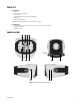
PARTS LIST Qty 1 1 1 1 1 3 Description Camera Ferrite (for Class B compliance) 6-pin connector IX Series and IXE Series Quick Start Guide (C2951M) Resource disc MAC address labels (extra) Installation tools and the following parts are needed but not supplied: Qty 1 1 1 Description Lens (use either a megapixel or standard auto iris lens, depending on the camera model) Service cable (IX-SC) Mounting hardware ACT CAMERA LAYOUT 24V~ RELAY ALARM ACC RESET LINK PoE R1 A1 (FRONT COVER OPENED) F V F
ì RJ-45 Connector: Supplies power to the camera through the network using PoE. If PoE is not available, the camera is prewired for 24 VAC. î ï ñ ó Ethernet Activity LED: Flashes green to indicate that data is being transmitted/received by the camera. r Reset Button: Reboots the camera or restores the camera's factory default settings. This button is recessed. Using a small tool, such as a paper clip, press and release the reset button once to reboot the camera.
Installation 1. Remove all of the contents from the shipping box. 2. Install the lens: NOTE: Megapixel lenses are designed and tested to deliver optimal image quality to megapixel cameras. A standard definition lens installed on a megapixel camera will limit the resolution of the camera and create poor image quality. a. Make sure the lens does not touch the camera imager when installed. Screw the lens onto the lens mount. Be careful to prevent dust from entering the space between the lens and the imager.
Figure 5. Ferrite Installation WARNING: The ferrite must be installed for the camera to meet FCC Class B compliance standards. Failure to correctly install the ferrite might cause harmful interference to radio communications. 6. Connect the necessary wiring for alarms and relays (refer to Wiring on page 14). 7. Apply power to the camera.
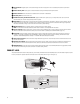
SERVICE CABLE The camera includes a service connector that outputs camera video. Use it at the installation site to set up the field of view and to focus the camera. Pelco offers an optional service cable (IX-SC) that plugs directly into the service connector. To access the service connector, you must slide the front cover down (refer to Figure 1 on page 9). This service cable has a male BNC output for most standard viewers. NOTE: The ICS-SC and CST150 are not compatible with this camera.
WIRING CAT5 CABLE Connect a Cat5 cable to the RJ-45 network connector. The 8-pin connector includes video and PoE for the camera. PoE (IEEE 802.3af) injects power over the same cabling that carries the network data, eliminating the need for a separate power supply. This simplifies the installation and operation of the camera without any degradation of network performance. NOTE: The camera will autosense and work with either a crossover cable or straight cable. Refer to Figure 7 for pin descriptions.
Connecting a Relay Device The camera has an output for activating an external device. It supports both momentary and continuous relay operation. You can operate the relay interactively during an active connection, or it can operate automatically to coincide with certain events. Typical applications include turning on lights or other electrical devices or activating a door, gate, or lock. WARNING: Do not exceed the maximum rating of 12 VDC, 0.15 A.
Unsupervised Alarms When an alarm is configured as an unsupervised alarm, the camera only activates an alarm when the normal alarm state (open or closed) changes. Figure 12 illustrates the alarm and no alarm conditions of an unsupervised alarm input. NORMALLY CLOSED NO ALARM GND NORMALLY OPEN +V NO ALARM GND +V ALARM GND +V ALARM GND +V ALARM GND +V NO ALARM GND +V +V ALARM GND CUT NO ALARM GND CUT +V BYPASS BYPASS Figure 12.
Operation Installation must be complete before you can begin operating the camera (refer to Installation on page 11). The camera completes a configuration sequence when power is applied; the green LED flashes five times per second for approximately two minutes, and then glows solid green indicating the sequence is complete. NOTE: If the camera is not connected to a DHCP server and DHCP is enabled, the configuration sequence might take up to five minutes to complete.
Live Video Page The live video page allows you to manage the way you view live video and capture images. You can also view live video from this page and access menus on the navigation bar (based on user permissions). Figure 15. Live Video Page LIVE VIDEO PAGE ICONS Viewable icons are based on user permissions. Show Device List: Displays a list of viewable cameras connected to the same VLAN as the camera to which you are logged on. Disable Viewer: Closes the live view window.
SELECT A STREAM 1. Click the Select Stream button. 2. Select one of the following stream options: Primary Stream: To select this stream, click the button next to Primary Stream; the stream settings appear. Secondary Stream: To select this stream, click the button next to Secondary Stream; the stream settings appear. QuickView Stream: To select this stream, click the button next to QuickView Stream; the stream settings appear. This is a fixed, low resolution, low bit rate, JPEG stream.
MAXIMIZE THE VIEWING AREA 1. Click the Maximize Viewing Area button. The live video pane expands to the full size of the page. 2. Click the “Take a Snapshot” button to capture a video image. 3. Click the Show Toolbar button to return to the normal view. OPEN THE STREAM IN A NEW WINDOW 1. Click the “Open Stream in New Window” button. A new, independent window opens displaying the live video. 2. Drag the lower-right corner of the window to resize the window. 3.
Settings Page Depending on user permissions, the Settings page allows you to manage camera system settings, set up users and groups, and control the camera. NOTE: The Settings menu might not be available if the user does not have permission to access this feature (refer to Users on page 43). To access the camera settings: 1. Log on to the camera. 2. Click the Settings link in the navigation bar located in the upper-right corner of the page; a list of menu tabs appears.
SYSTEM TAB Use the System tab to view the device’s current firmware version, change the device name, enable/disable the power LED, and set up a server for event system email. Figure 17. System Settings Page GENERAL SETTINGS Device Name: The user-friendly description of the camera. This name is displayed in the gray area near the top of all pages. Enable LED: Select Off to disable the power LED located on the front of the camera. The default setting is On.
TIME SETTINGS Select the time server and time zone for the camera, and turn on or off the overlay. Time Server: The external server that uses Network Time Protocol (NTP) to synchronize the camera date and time settings. Time Zone: The geographic area that is closest to the camera’s physical location. Overlay: Select On to overlay the date and time on all video streams. Select Off to turn off the date and time overlay. Current Date: A read-only field that displays the date and time of the camera.
NETWORK TAB Use the Network tab to manage general settings, configure Secure Socket Layers (SSL), and enable SSH (Secure Shell). GENERAL This page includes a list of general network communication settings. Figure 18. Network Settings Page Hardware Address: A read-only field that displays the MAC address for the camera. Hostname: The user-friendly hostname of the device, which is registered with the Domain Name System (DNS) server.
DHCP Off Turning off DHCP allows you to manually set the camera’s IP address. WARNING: Contact your network administrator to avoid any network conflicts before setting/changing the IP address of the device. To turn off DHCP: 1. Select the Off option for DHCP. 2. Change the following network settings, as required: • IP Address • Subnet Mask • Gateway • DNS Server 3. Click the Save button to save the settings, or click the Reset button to clear all of the information you entered without saving it.
Generate Certificate Request 1. Click the Install Certificate button located at the bottom of the SSL Configuration page. The Select Certificate Install Method option buttons appear on the page. 2. Select Generate Certificate Request, and then click Next. The Certificate Request Form opens. 3. Fill out all of the fields, and then click Generate Request. “Generating certificate signing request, please wait” appears on the page. 4.
SSH WARNING: This is an advanced control intended for troubleshooting camera issues. To prevent damage to the camera, only use this setting with guidance from Pelco Product Support. Contact Pelco Product Support at 1-800-289-9100 (USA and Canada) or +1-559-292-1981 (international) for assistance. SSH (Secure Shell) is a user-enabled protocol that allows Pelco Product Support to log on to and service the camera for advanced troubleshooting purposes.
IMAGING TAB Use the Imaging tab to change the camera orientation or to adjust digital processing, exposure, focus, tone map, and white balance. GENERAL The general imaging settings allow you to change the camera’s orientation and adjust digital processing. Figure 21. Orientation and Digital Processing Page Orientation The camera can be installed in a standard or inverted position. When installed for inverted operation, the camera orientation needs to be reconfigured for normal operation.
Digital Processing The digital processing settings adjust the camera’s sharpness, saturation, and contrast. Digital processing can be set to Auto or Manual. When set to Auto, the camera continually delivers the best possible image by automatically adjusting the digital processing settings based on the scene. Auto is the default setting. Manual digital processing is recommended only for indoor applications that have a single, unchanging primary light source.
EXPOSURE Exposure is the amount of light detected by the camera sensor. A scene with correct exposure settings has adequate detail and contrast between white and dark values. An image with too little or too much exposure eliminates detail in the scene. The camera features auto and manual exposure settings. Auto is the default setting. Figure 22.
Auto Exposure Auto exposure automatically sets the amount of light detected by the camera sensor based on settings for light control, exposure compensation, and the day and night exposure times. Light Control: Sets the mechanism that controls the exposure time of the camera. Light control settings include Digital Exposure and Auto-Iris control. When Light Control is set to Digital Exposure, the camera controls the exposure time.
Manual Exposure Manual exposure sets the amount of light detected by the camera sensor based on a user-defined setting. Manual exposure is recommended only for indoor applications that have a single unchanging primary light source. Figure 23. Manual Exposure Page Analog Gain: The amount of gain applied across all color channels prior to image processing. Increasing the gain increases the brightness of image, but it also increases the amount of noise in the image. The analog gain range is 1.00 to 15.
DAY NIGHT Day Night controls the position of the IR cut filter, which determines the color or black-white setting of the camera. The Day Night settings change depending on the Exposure settings. If the camera is set to Auto Exposure, the Day Night Mode can be set to Auto or Manual and all of the respective settings are available. If the camera is set to Manual Exposure, the only available Day Night setting is Position (refer to Manual Day Night).
FOCUS Use the Focus page to select either Auto back focus or Manual back focus, adjust the available settings, or reset the back focus to factory defaults. NOTE: It is recommended to set focus to Manual when using analytics. If focus is set to Auto, significant background changes will occur when the camera auto-adjusts to different points within a scene resulting in frequently changing image sharpness.
Manual Focus Manual focus turns off the auto focus mechanism and locks the camera at a user-specified position. The camera will not focus if changes in the scene occur. This setting is recommended for indoor applications that have a single unchanging primary light source or for video analytic applications. Figure 25. Manual Focus Page (Day/Night Camera) When changing from auto focus to manual focus, the current auto settings are retained as defaults for all of the manual settings.
TONE MAP Tone map balances the brightest and darkest sections of an image to produce a picture with more balanced lighting and more detail. This is accomplished, in part, when the device maps the 10-bit input sensor data (0 to 1023 bits) into 8-bit output RGB values (0 to 255 bits). Use the sliders to easily adjust an image's black clip percent, white clip percent, and gamma correction. Figure 26.
WHITE BALANCE White balance settings define how the camera processes video images to render true colors in a scene. White balance is especially effective in scenes with changing lighting conditions or in scenes with more than one type of light source. For example, scenes that benefit from white balance correction are outdoor scenes, indoor scenes that include a window or door that opens to the outdoors, or indoor scenes that include both incandescent and fluorescent lighting.
Manual White Balance While the Auto mode will cover most scenes, the camera cannot account for every possible scene. In some installations, use manual white balance to render the most accurate image color possible. NOTE: Manual white balance is recommended only for indoor applications that have a single unchanging primary light source. Figure 28.
VIDEO STREAMS TAB Use the Video Streams tab to select a preset camera configuration or to configure custom video stream settings. SELECT PRESET Several preset camera configurations, which include primary and secondary video stream settings, are available for easy setup. These preset configurations are different depending on camera model. Refer to Custom Configuration on page 40 to configure custom video streams. Figure 29. Select Video Stream Configuration Page To select a preset camera configuration: 1.
CUSTOM CONFIGURATION The camera features dual video streams with programmable settings for compression, resolution, image rate, and bit rate. The default names for the streams are Primary and Secondary. Although each stream can be programmed independently, the settings of one stream can limit the options available for the other stream depending on the processing power used. Figure 30.
Compression Standards JPEG: A commonly used compression scheme, also known as MJPEG. JPEG has the least impact on the camera's processor but requires the most bandwidth. H264: A new version of MPEG-4 compression used in high-definition video players such as Blu-ray™ and HD-DVD. H.264 is the most processor-intensive but requires the least amount of bandwidth. Resolution Resolution is the overall size of the image. Refer to the following table for the resolution capabilities of your camera model. Table B.
Rate Control The rate control setting determines the bit rate and quality of each frame in the video stream. There might be a trade-off between image quality and the resources required for video storage when selecting a rate control setting. CBR: The constant bit rate (CBR) streams video at a fixed number of bits per second. CBR uses the full capacity of the bit rate setting for scenes with or without motion. Video is always streamed at the user bit rate setting.
USERS AND GROUPS TAB Use the Users and Groups tab to create and manage user accounts, group permissions, and to change the way the camera manages the users and groups settings. USERS User accounts can be created and added to groups to limit the permissions given to individuals logged on to the camera. Use the features on this page to create, modify, or delete user accounts. Creating a New User Figure 31. New User Page To create a new user: 1.
8. Select the appropriate check boxes to choose the groups you wish to assign to the user. The Users tab includes default accounts for the following groups: • Select All: Selects all group definitions. • Administrators: This is the only defined group that cannot be deleted; however, the administrator password can be changed. For security purposes, it is important that you change your password after you log on to the device for the first time. This group has access to all permissions.
Deleting a User 1. Click the Users and Groups tab, and then select Users from the drop-down menu. 2. Click the user profile that you want to delete from the defined users section located in the box on the left side of the page. 3. Click the Delete User button. A dialog box appears with the message “Are you sure you want to delete the user?” 4. Click OK. The user profile is deleted from the defined user profiles section. NOTE: The “admin” user cannot be deleted.
GROUPS Groups can be created to assign permissions given to users within each group. Use the features on this page to create, modify, and delete groups and permissions. Multiple permissions can be assigned to each group. Creating a New Group Figure 33. New Group Page To create a new group: 1. Click the Users and Groups tab, and then select Groups from the drop-down menu. 2. Click in the Group Name box and type a name for the group you are creating (2 to 23 alphanumeric characters). 3.
Editing a Group Figure 34. Edit Group Page To edit a group: 1. Click the Users and Groups tab, and then select Groups from the drop-down menu. 2. Click the group profile that you want to edit from the box on the left side of the page. 3. Double-click in each of the text boxes to highlight the text. Type the new information in each text box. 4. Select or clear the appropriate check boxes from the groups list. 5.
GENERAL SETTINGS The user and groups general settings allow you to change the way the camera manages the users and groups settings. These settings can be managed on a camera-to-camera basis or by using a centralized server to apply changes to multiple cameras. Figure 35. User and Group Settings Page The available general settings for users and groups are as follows: Standalone: The camera manages its users and groups locally. Any changes to users and groups affect only the camera that you are accessing.
EVENTS TAB Use the Events tab to program sources and handlers to manage camera events. SOURCES An event is a preprogrammed camera function that is automatically activated by an event source. The camera supports three types of event sources. Alarm Source: The camera supports one alarm source. The sources are the camera inputs for external signaling devices, such as door contacts or motion detectors (refer to Alarm, Relay, and 24 VAC Connector on page 14).
Creating a Timer Event Source 1. Click the Events tab, and then select Sources from the drop-down menu. 2. Click in the Name box and type a user-friendly name (2 to 23 alphanumeric characters). 3. Select Timer from the Type drop-down menu. 4. Click in the Frequency box and type a number. Select seconds, minutes, hours, or days from the Frequency drop-down menu. 5. Click the Submit button to save the settings, or click the Reset button to clear all of the information you entered without saving it.
HANDLERS Event handlers are the actions that the camera takes when an event occurs. The camera supports four event handlers. Send Email: Sends an email to a defined email address when an event is activated. The SMTP server must be configured to accept the camera IP address. Write JPEG to SD Card: Saves a JPEG of the activated event to a mini SD card. An SD card must be installed in the device for this handler to function. NOTE: The mini SD card must be formatted as FAT32.
8. If you do not want the handler activated every time an event occurs, set filters for the handler (refer to Example Handler Filter Setup on page 53). a. Select the day(s) of the week on which you want emails to be sent. b. Type times in the Start and End boxes for the days you have selected. Use time values in 24-hour notation (for example, use 0800 for 8:00 a.m., 1600 for 4:00 p.m.). 9. Select one or more event sources to send an email when those event sources are activated. 10.
Creating an Open/Close Relay Event Handler 1. Click the Events tab, and then select Handlers from the drop-down menu. 2. Click in the Name box and type a user-friendly name (2 to 23 alphanumeric characters). 3. Select Open/Close Relay in the Type drop-down menu. 4. Move the On Time slider to set the amount of time that the relay will remain open. The time range is 0.1 to 200 seconds; the default setting is 0.1. 5. Move the Off Time slider to set the amount of time that the relay will remain closed.
Help Menu Online Help documents the basic instructions for configuring the camera. Click the Help hyperlink in the navigation bar to access these instructions. Log Off Menu To log off, click the Log Off button in the navigation bar. A login dialog box appears.
Specifications General Imaging Device 1/3-inch (effective) Imager Type CMOS Imager Readout Progressive scan Maximum Resolution 1920 x 1080 Signal-to-Noise Ratio 50 dB Auto Iris Lens Type DC drive Electronic Shutter Range 1~1/10,000 sec Wide Dynamic Range 60 dB White Balance Range 2,000° to 10,000°K Sensitivity Color (1x/33 ms) Color SENS (15x/500 ms) Mono (1x/33 ms) Mono SENS (15x/500 ms) f/1.2; 2850°K; SNR >24 dB 0.50 Lux 0.12 Lux 0.25 Lux 0.
0.9 1280 720 16:9 30.0 ips 10.0 Mbps 30.0 ips 2.9 Mbps 0.5 800 600 4:3 30.0 ips 7.7 Mbps 30.0 ips 2.0 Mbps 0.3 640 512 5:4 30.0 ips 5.2 Mbps 30.0 ips 1.6 Mbps 0.3 640 480 4:3 30.0 ips 4.9 Mbps 30.0 ips 1.5 Mbps 0.2 640 352 16:9 30.0 ips 3.6 Mbps 30.0 ips 1.2 Mbps 0.2 480 368 4:3 30.0 ips 2.8 Mbps 30.0 ips 1.0 Mbps 0.1 480 272 16:9 30.0 ips 2.0 Mbps 30.0 ips 0.8 Mbps 0.1 320 256 5:4 30.0 ips 1.3 Mbps 30.0 ips 0.5 Mbps 0.1 320 240 4:3 30.
C2953M-A (5/09) 57
PRODUCT WARRANTY AND RETURN INFORMATION WARRANTY Pelco will repair or replace, without charge, any merchandise proved defective in material or workmanship for a period of one year after the date of shipment.
www.pelco.com Pelco, Inc.