® PMC14E Series High-Resolution 14-Inch Color Monitors Installation/Operation Manual C929M-B (2/97) Pelco • 3500 Pelco Way, Clovis, CA 93612-5699 • USA • (800) 289-9100 or (1-559) 292-1981 FAX (800) 289-9150 or (1-559) 292-3827 International customers call 1-559-292-1981 or FAX 1-559-348-1120
CONTENTS Section Page 1.0 GENERAL .................................................................................................. 1 1.1 IMPORTANT SAFEGUARDS AND WARNINGS ............................... 1 2.0 DESCRIPTION .......................................................................................... 4 2.1 MODELS ............................................................................................ 4 2.2 OPTIONAL ACCESSORIES .............................................................
1.0 GENERAL 1.1 IMPORTANT SAFEGUARDS AND WARNINGS Prior to installation and use of this product, the following WARNINGS should be observed. 1. Installation and servicing should only be done by Qualified Service Personnel and conform to all Local codes. 2. Unless the unit is specifically marked as a NEMA Type 3, 3R, 3S, 4, 4X ,6 or 6P enclosure, it is designed for Indoor use only and it must not be installed where exposed to rain and moisture. 4. Only use replacement parts recommended by Pelco. 5.
1.1 IMPORTANT SAFEGUARDS 1. Read Instructions - All the safety and operating instructions should be read before the unit is operated. 2. Retain Instructions - The safety and operating instructions should be retained for future reference. 3. Heed Warnings - All warnings on the unit and in the operating instructions should be adhered to. 4. Follow Instructions - All operating and use instructions should be followed. 5. Cleaning - Unplug the unit from the outlet before cleaning.
13. Power Lines - An outdoor system should not be located in the vicinity of overhead power lines or other electric light or power circuits, or where it can fall into such power lines or circuits. When installing an outdoor system, extreme care should be taken to keep from touching such power lines or circuits as contact with them might be fatal. U.S.A. models only - refer to the National Electrical Code Article 820 regarding installation of CATV systems. 14.
2.0 DESCRIPTION The PMC14E Series provides 14-inch (36 cm), color, high-resolution monitors. Monitor Features • Two video and audio input channels (one passive) with looping output. Video inputs include connectors for either a standard composite video signal or Y/C (Super VHS) signal.
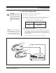
3.0 INSTALLATION 3.1 BACK PANEL CONNECTIONS CAUTION: Do not install this monitor in an excessively hot location, or in any way obstruct the ventilation openings in the cabinet. Premature component failure or damage to the cabinet may result. Refer to Table A for the type of video coaxial cable to use. Refer to Figure 1 for rear panel connections. Connect equipment to the monitor as follows. There are several options for inputs 1 and 2 as shown on this and the following pages. Select the appropriate one.
Input 1 or 2 (Input from Switcher or Matrix Control System - Video Only) 1. Refer to Figure 3. Connect the video output from the video switcher or matrix control equipment to Input 1 or Input 2 on the output monitor. 2. Set the 75-ohm/HIGH switch for 75 ohms if you are using Input 1. OUTPUT MONITOR VIDEO SWITCHER OR MATRIX SET FOR 75 OHMS IN OUT 75 ohm HIGH INPUT 2 VIDEO VIDEO OUTPUT INPUT 1 AUDIO AUDIO VIDEO 2 AUDIO VIDEO AUDIO AC INPUT INPUT OUTPUT INPUT OUTPUT Figure 3.
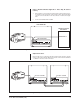
Input 1 (Dedicated Monitor Application - Video Only, No Camera Control) 1. Refer to Figure 5. Connect the video cable from the camera to the IN connector of Input 1 on the feed monitor. Connect another video cable from the OUT connector of the feed monitor to the video switcher or matrix control equipment. 2. Set the 75-ohm/HIGH switch for HIGH.
VTR Connections Refer to Figure 7. Connect the video and audio connections from the monitor to a video recorder if desired. Power Plug the appropriate end of the power cable into the AC INPUT on the monitor. Plug the other end into a utility outlet. IN OUT 75 ohm HIGH INPUT 2 VIDEO VIDEO AUDIO OUTPUT INPUT 1 AUDIO VIDEO 2 AUDIO VIDEO AUDIO AC INPUT INPUT OUTPUT INPUT OUTPUT VIDEO IN AUDIO IN VIDEO OUT AUDIO OUT Figure 7.
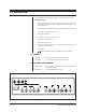
3.2 FRONT PANEL CONTROLS Refer to Figure 8. Set the controls on the front panel of the monitor as follows: 1. Set the PAL/NTSC switch for NTSC video format if you have a PMC14E monitor. Set the switch for PAL video format if you have a PMC14EX monitor. 2. Set the VTR/VIDEO switch for the signal input that you are using. 3. • Select VTR if you want to play a VCR that is connected to the VTR terminals on the back of the monitor.
4.0 OPERATION There are two sources of video and audio input: • VTR (video tape recorder) • Video 1 and Video 2 Only one source can be selected at a time. To select the input from a video recorder, set the VTR/VIDEO switch on the front panel in the VTR position. In this position, the video and audio signals are sent to the monitor and through the OUTPUT connectors to any equipment connected to them. To select the input from Video 1 and/or Video 2: 1.
5.0 MAINTENANCE To reduce the risk of electric shock, do not remove the cover or back. No userserviceable parts are inside. Refer servicing to qualified personnel. Some household aerosol sprays, cleaning agents, solvents, or polishes may damage the cabinet finish. Clean the cabinet with water and mild soap. Use a soft cloth for drying. If the quality of the picture on the monitor is poor and cannot be improved, inspect all system connections and cable runs.
6.0 SPECIFICATIONS ELECTRICAL Input Power PMC14E PMC14EX 120 VAC, 60 Hz 230 VAC, 50 Hz Power Consumption PMC14E 65 W PMC14EX 70 W System PMC14E PMC14EX NTSC (525 lines, 60 fields per second) PAL (625 lines, 50 fields per second) Picture Tube: 14 inches (36 cm) measured diagonally Effective Picture Size Height: 8.27 inches (21.0 cm) Width: 11.0 inches (28.0 cm) Input Signal: Composite video, negative synch -Y: 1.0 Vp-p -C: 0.286 Vp-p Subcarrier Frequency Synch Range at Room Temperature: 3.
GENERAL Dimensions: 13.8" W x 12.4" H x 14.6" D (35 x 31.5 x 37.1 cm) Finish: Steel cabinet painted dark gray. Black bezel around the screen. Operating Temperature: 32° to 104° F (0° to 40° C) Humidity: 0% to 90% (non-condensing) Connectors Video Input, Output: Y/C Input, Output: Audio Input, Output: VTR Input, Output: Pelco Manual C929M-B (2/97) BNC 4-pin mini-Din RCA RCA Power Cord: PMC14E PMC14EX 3-wire power cord with grounded plug “Euro” style grounded power cord Weight Shipping: 31.
7.0 WARRANTY AND RETURN INFORMATION WARRANTY Pelco will repair or replace, without charge, any merchandise proved defective in material or workmanship for a period of one year after the date of shipment. Exceptions to this warranty are as noted below: • Five years on FT/FR8000 Series fiber optic products. • Three years on Genex® Series products (multiplexers, server, and keyboard).