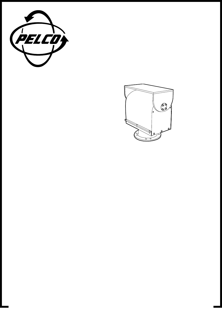
® PT1250 Series PT1250DC Series PT1253R PT1250 EX/AMS PT1260EX Series PT1280 Series Heavy-Duty Pan/Tilts Maintenance/ Service Manual C373SM-A (8/01) Pelco • 3500 Pelco Way, Clovis • CA 93612-5699 USA • www.pelco.
CONTENTS Section Page IMPORTANT SAFEGUARDS AND WARNINGS ................................................................ 4 DESCRIPTION ................................................................................................................... 5 MODELS .................................................................................................................... 5 OPTIONS ...................................................................................................................
LIST OF TABLES Table A B C D E F G H I J K L M N O P Q Pelco Manual C373SM-A (8/01) Page PT1250 Series Mechanical Parts List ............................................................... 10 PT1250 Series Hardware List ........................................................................... 13 PT1250DC Series Parts List ............................................................................. 15 PT1253R Mechanical Parts List ........................................................................
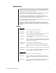
IMPORTANT SAFEGUARDS AND WARNINGS Prior to installation and use of this product, the following WARNINGS should be observed. 1. Installation and servicing should only be done by qualified service personnel and conform to all local codes. 2. Unless the unit is specifically marked as a NEMA Type 3, 3R, 3S, 4, 4X, 6 or 6P enclosure, it is designed for indoor use only and it must not be installed where exposed to rain and moisture. 3. Only use replacement parts recommended by Pelco. 4.
DESCRIPTION All heavy duty pan/tilts can operate with loads up to 100 pounds (45.4 kg). Rugged hightorque motors with adjustable worm-gear final drives ensure long operational life and driftfree operation. All models are manufactured from cast and/or plate aluminum with all internal parts corrosion-protected steel or aluminum. The PT1250 Series and PT1280 Series are capable of auto/random scan operation with the addition of the Pelco solid-state auto/random scan joystick control.
PT1250DC/PP Same as PT1250DC except supplied with position feedback modification. Requires preset control or control with AZL option (panel readout meters) PT1250DC/RAD Same as PT1250DC except supplied with radiation resistant wiring and white epoxy paint. Low level radiation resistant up to 106 rads PT1253R PT1253R Heavy duty, indoor/outdoor pan/tilt, 120 VAC.
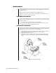
MAINTENANCE Inspect the pan/tilt unit every six months to ensure trouble-free operation and an extended product life. Harsh environments and/or continuous motion applications may require more frequent maintenance. Please read all of the instructions that follow before servicing the pan/tilt. To begin, remove the three screws on the front of the pan/tilt housing and lift the cover to gain access to the pan and tilt motor assemblies. TIGHTENING DRIVE CHAINS Check the pan and tilt drive chains for tension.
RESETTING POTENTIOMETERS IMPORTANT: Be very careful when resetting potentiometer switches. Be sure that the pan/tilt has been centered between maximum pan and tilt travel, regardless of the adjustable limit stops. Failure to observe caution when resetting potentiometers could result in damage to the preset positioning ability of the pan/tilt. Models with Preset Positioning (PP) 1.
EXPLODED ASSEMBLY DIAGRAMS Figure 3.
Table A.
Table A.
Figure 4.
Table B.
Figure 5.
Table C.
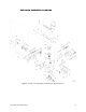
35 31 22 52 33 32 34 49 48 3 20 17 13 4 16 20 7 20 43 17 11 14 13 16 19 12 45 20 40 44 12 18 5 18 20 41 15 30 10 42 45 2 44 14 18 6 38 29 39 18 46 19 20 9 25 26 15 36 37 9 8 8 27 25 24 9 23 47 9 6 7 28 54 21 1 50 01172 Figure 6.
Table D. PT1253R Mechanical Parts List Item Qty 1 2 3 4 5 6 7 8 9 10 11 12 13 14 15 16 17 18 19 20 21 22 23 24 25 26 27 28 29 30 31 32 33 34 35 36 37 38 39 40 41 42 43 44 45 46 47 48 49 50 51 52 53 54 1 1 1 1 1 2 2 2 4 1 1 2 2 2 2 8 4 4 2 6 1 1 1 1 4 2 2 1 1 2 1 1 1 1 1 1 1 1 1 1 1 1 1 2 2 1 1 1 2 1 1 7 ft. 3 Description Gasket, connector Nut, pan spindle black no.
Z B E BB AA Y J CC BB N M F E Z B I H K N F F C G T F I H DD A K E M M C E T U A W L G P S L P U T V U D S R 01173 Figure 7.
Table E. PT1253R Hardware List Item Qty A B C D E F G H I J K L M N P R S T U V W X Y Z AA BB CC DD 4 5 4 6 9 4 8 8 8 2 8 8 5 2 4 4 6 3 6 4 4 3 6 5 3 5 1 1 Pelco Manual C373SM-A (8/01) Description Screw, 1/4-20 x .
Pelco Manual C373SM-A (8/01) Figure 8.
Table F.
Table F.
Figure 9.
Table G.
Table H.
35 31 22 52 33 32 34 49 48 3 20 17 13 4 16 20 7 20 43 17 13 11 14 16 ** 56 ** 55 12 19 45 20 40 44 12 18 5 18 20 41 15 30 10 42 45 14 2 44 18 6 29 39 19 * 25 * 26 38 46 9 * 36 * 53 18 20 15 37 9 8 * 8 27 25 24 9 * 23 *PT1280P ONLY **PT1280SL ONLY 47 * 9 6 7 28 54 * 21 51 1 50 01151 Figure 10.
Table I. PT1280P and PT1280SL Mechanical Parts List Item Qty 1 2 3 4 5 6 7 8 9 10 11 12 13 14 15 16 17 18 19 20 21 22 23 24 25 26 27 28 29 30 31 32 33 34 35 36 37 38 39 40 41 42 43 44 45 46 47 48 49 50 51 52 53 54 55 56 1 1 1 1 1 2 2 2 (1) 4 (2) 1 1 2 2 2 2 8 4 4 2 6 1 1 1 1 4 (2) 2 2 1 1 2 1 1 1 1 1 1 1 1 1 1 1 1 1 2 2 1 1 1 2 1 2 7 FT 1 3 1 1 Description Gasket, connector Nut, pan spindle black no.
Z B E BB AA Y J CC BB N ** X F M U ** W ** E Z B K I H F F C G N T K I H F DD A E M M C E U * W * A T U * L G P *PT1280 Only **PT1280SL Only S L P * U * T * U V D S 01152 R Figure 11.
Table J. PT1280P and PT1280SL Hardware List Item Qty A B C D E F G H I J K L M N P R S T U V W X Y Z AA BB CC DD 4 5 4 6 9 4 8 8 8 2 8 8 (4) 5 2 4 4 6 3 6 (4) 4 2 (2) 3 6 5 3 5 1 1 Description Screw, 1/4-20 x .
35 31 22 52 33 32 48 34 49 65 3 66 67 20 4 7 57 17 * 68 59 ** 56 13 16 20 20 16 13 17 20 43 12 11 14 ** 64 30 44 44 ** 63 18 20 * 62 45 ** 55 19 5 18 41 15 45 42 2 6 * 25 * 26 * 23 38 60 39 19 * PT1280P/PP Only ** PT1280SL/PP Only 40 12 46 9 * 36 * 8 * 53 * 9 6 18 10 14 29 58 15 37 9 8 61 20 27 18 25 28 24 9 47 7 54 * 21 1 50 51 01153 Figure 12.
Table K. PT1280P/PP and PT1280SL/PP Mechanical Parts List Item Qty 1 2 3 4 5 6 7 8 9 10 11 12 13 14 15 16 17 18 19 20 21 22 23 24 25 26 27 28 29 30 31 32 33 34 35 36 37 38 39 40 41 42 43 44 45 46 47 48 49 50 51 52 53 54 55 56 57 58 1 1 1 1 1 2 2 2 (1) 4 (2) 1 1 2 2 2 2 8 4 4 2 6 1 1 1 1 4 (2) 2 (0) 2 1 1 2 1 1 1 1 1 1 (0) 1 1 1 1 1 1 1 2 2 1 1 1 2 1 2 7 FT 1 3 1 1 1 1 59 1 Description Gasket, connector Nut, pan spindle, black no.
Table K. PT1280P/PP and PT1280SL/PP Mechanical Parts List (Continued) Item Qty 60 1 61 1 62 63 64 65 66 67 68 1 1 1 1 1 1 1 Description Part Number Pot model 534 5K OHM Pot, dual arm pre res Gear potentiometer Gear 1.875 plastic Collar, pan AZL gear Hub, PP pan gear Gear, pan spindle feedback SL Gear, polycarb Bracket, AZL potentiometer Pot, model 534 5K OHM Gear, AZL collar, polycarb POT005.0K10534 (P/PP only) POTDARM01.
Table L. PT1280P/PP and PT1280SL/PP Hardware List Item Qty A B C D E F G H I J K L M N P R S T U V W X Y Z AA BB CC DD 4 5 4 6 9 6 8 8 (10) 8 (10) 2 8 8 (4) 5 2 8 4 10 3 10 (6) 4 6 (2) 3 6 5 3 5 1 2 Description Screw 1/4-20 x .
WIRING DIAGRAMS Table M. PT1250 Series Electrical Parts List Parts are for all models unless specified otherwise Symbol C1, C2 C3 M1, M2 — — R1, R2 S1-S4 S1-S4 S1-S4 — — — — — — Description Capacitor, 6 MFD, 250 VAC (except 220 model) Capacitor, 1.
Figure 15. PT1250 Series Wiring for RAD Model Figure 16.
Figure 17. PT1250DC Wiring Diagram Table N. PT1250DC Electrical Parts List 36 Quantity Symbol Description Manufacturer Part Number 8 C1-8 Capacitor .0047/1kv CDE CAPU0.0047/1000 4 C9-12 Capacitor .1/400V Sprague CAPU0000.1/400 4 L1-4 Choke 100mh Miller CHO5250 2 M1-2 Motor Pelco MR02-0002-3104 1 P1 Connector AMP CON206705-1 9 — Connector Pin AMP CON66103-2 4 R1-4 Resistor 47ohm 1/4W — RES047.0-.25 2 — P.C.
Figure 18. PT1250DC/PP Wiring Diagram Table O. PT1250DC/PP Electrical Parts List Quantity Symbol Description Part Number 8 C1-8 Capacitor .0047/1kv CAPU0.0047/1000 4 C9-12 Capacitor .1/400V CAPU0000.1/400 4 L1-4 Choke 100mh CHO5250 2 M1-2 Motor MR02-0002-3104 1 P1 Connector CON206036-1 4 R1-4 Resistor 47 ohm 1/4W RES047.0-.25 2 R5-6 Pot 5K Ten Turn POT005.0K10534 2 — P.C. Assembly 1551016COMP 1 — Mating Connector Assy.
Figure 19.
Figure 20.
Table P. 12501007ACOMP Frame Scan Parts List 40 Schematic Quantity C7 C2 C4A, C6A C3, C4 C1A, C7A C5, C10 C6 C1 C8 C9 M4610 Input Connector CR4, CR5, CR6, CR7 CR3 CR1, CR2 4011 4027 4060 4093 R17 K1, K2 R5A, 10R4, 11R3 R9, R13A, R13B, R15A R1 R2 R12 R13 R6, R7, R8 R5, R10, R14 R11, R15 1 1 2 2 2 2 1 1 1 1 2 1 4 1 2 1 1 1 1 1 2 3 4 1 1 1 1 3 3 2 Component Description CAP 500PF 600V radial CAP .022MF 100V AZ CAP .01M 1000V radial disc CAP .01MF 16V radial CAP .1M 400V axial CAP .
Figure 21. PT1250EX/AMS Wiring Diagram Table Q. PT1250EX/AMS Electrical Parts List Symbol Description Part Number C1, C2 C3 M1, M2 — — S1-S4 S1-S4 — T — Capacitor, 6 MFD, 250 VAC Capacitor, 1 MFD, 600 V Pan and tilt motors Motor gearhead Potentiometer, 5K ohm Switch Switch actuator Heater blanket, 40 watts each Thermostat Mating connector assembly CAPU0006.0/250N CAPU0001.0/600 12508110 12508111 POT005.
BRN S1 RED BLUE M1 C1 S2 S3 ORG YEL C2 C3 M2 S4 GRN Quantity Symbol Description Part Number 1 C1, C2 Capacitor, 6 MFD 250 VAC CAPU0006.0/250N 1 C3 Capacitor, 1 MF 600V CAPU0001.0/600 1 M1 Pan Motor 12508110 1 M2 Tilt Motor 12508110 2 — Motor Gearhead 12508111 4 S1–S4 Switch SWI1SM1 Figure 22.
S1 LEFT RIGHT RED BLUE M1 C1 S2 PRESET COMMON W/BLK PAN PRESET W/GRN TILT PRESET W/VIO PRESET +5V W/BRN RIGHT LEFT 3 PAN R1 5K 1 DOWN UP 1 TILT R2 5K 3 S3 UP DOWN ORG YEL COMMON GROUND BRN GRN C2 C3 M2 S4 01164 PT1260EX/PP Quantity Symbol Description Part Number 2 C1, C2 Capacitor, 6 MF 250V CAPU0006.0/250N 1 4 1 1 2 2 C3 S1–S4 M1 M2 — R1, R2 Capacitor, 1 MF 600V Switch Pan Motor Tilt Motor Gear Head Pot CAPU0001.0/600 SWI1SM1 12508110 12508110 12508111 POT005.
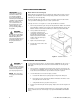
CAMERA ENCLOSURE MOUNTED HERE BOTH OF THESE FEED-THROUGHS GO TO THE CAMERA ENCLOSURE OTHER CONTROL SIGNAL FEED-THRU (THIS REPRESENTS ONLY A PORTION OF THE WIRING THAT ENTERED THE PAN/TILT HOUSING VIA THE P1 CONNECTOR) COAX VIDEO FEED-THRU P1 CONNECTOR FROM CONTROLLER (ALL CONTROL AND POWER FUNCTIONS ENTER THE PAN/TILT HOUSING THROUGH THIS CONNECTOR).
CAMERA ENCLOSURE MOUNTED HERE BOTH OF THESE FEED-THROUGHS GO TO THE CAMERA ENCLOSURE OTHER CONTROL SIGNAL FEED-THRU (THIS REPRESENTS ONLY A PORTION OF THE WIRING THAT ENTERED THE PAN/TILT HOUSING VIA THE P1 CONNECTOR) COAX VIDEO FEED-THRU P1 CONNECTOR FROM CONTROLLER (ALL CONTROL AND POWER FUNCTIONS ENTER THE PAN/TILT HOUSING THROUGH THIS CONNECTOR).
CAMERA ENCLOSURE MOUNTED HERE BOTH OF THESE FEED-THROUGHS GO TO THE CAMERA ENCLOSURE OTHER CONTROL SIGNAL FEED-THRU (THIS REPRESENTS ONLY A PORTION OF THE WIRING THAT ENTERED THE PAN/TILT HOUSING VIA THE P1 CONNECTOR) COAX VIDEO FEED-THRU P1 CONNECTOR FROM CONTROLLER (ALL CONTROL AND POWER FUNCTIONS ENTER THE PAN/TILT HOUSING THROUGH THIS CONNECTOR).
CAMERA ENCLOSURE MOUNTED HERE BOTH OF THESE FEED-THROUGHS GO TO THE CAMERA ENCLOSURE OTHER CONTROL SIGNAL FEED-THRU (THIS REPRESENTS ONLY A PORTION OF THE WIRING THAT ENTERED THE PAN/TILT HOUSING VIA THE P1 CONNECTOR) COAX VIDEO FEED-THRU P1 CONNECTOR FROM CONTROLLER (ALL CONTROL AND POWER FUNCTIONS ENTER THE PAN/TILT HOUSING THROUGH THIS CONNECTOR).
WARRANTY AND RETURN INFORMATION WARRANTY Pelco will repair or replace, without charge, any merchandise proved defective in material or workmanship for a period of one year after the date of shipment. Exceptions to this warranty are as noted below: • Five years on FT/FR8000 Series fiber optic products. • Three years on Genex® Series products (multiplexers, server, and keyboard).