O P E R A T I O N / C O N F I G U R AT I O N DX4700/DX4800 Series Hybrid Video Recorder Server Software Application C4655M (2/11)
C4655M (2/11)
Contents Description. . . . . . . . . . . . . . . . . . . . . . . . . . . . . . . . . . . . . . . . . . . . . . . . . . . . . . . . . . . . . . . . . . . . . . . . . . . . . . . . . . . . . . . . . . . . . . . . . . . . . . . . . . . 7 Client Application Software . . . . . . . . . . . . . . . . . . . . . . . . . . . . . . . . . . . . . . . . . . . . . . . . . . . . . . . . . . . . . . . . . . . . . . . . . . . . . . . . . . . . . . . . . 7 Product Overview. . . . . . . . . . . . . . . . . . . . . . . . . .
Alarm Recording . . . . . . . . . . . . . . . . . . . . . . . . . . . . . . . . . . . . . . . . . . . . . . . . . . . . . . . . . . . . . . . . . . . . . . . . . . . . . . . . . . . . . . . . . . . . 45 Motion Recording . . . . . . . . . . . . . . . . . . . . . . . . . . . . . . . . . . . . . . . . . . . . . . . . . . . . . . . . . . . . . . . . . . . . . . . . . . . . . . . . . . . . . . . . . . . 45 Text Recording . . . . . . . . . . . . . . . . . . . . . . . . . . . . . . . . . . . . . . . . . . . . . .
List of Illustrations 1 2 3 4 5 6 7 8 9 10 11 12 13 14 15 16 17 18 19 20 21 22 23 24 25 26 27 28 29 30 31 32 33 34 35 36 37 38 39 40 41 42 43 44 45 46 47 C4655M (2/11) Application Window . . . . . . . . . . . . . . . . . . . . . . . . . . . . . . . . . . . . . . . . . . . . . . . . . . . . . . . . . . . . . . . . . . . . . . . . . . . . . . . . . . . . . . . . . . . . . . 8 GUI Toolbar . . . . . . . . . . . . . . . . . . . . . . . . . . . . . . . . . . . . . . . . . . . . . . . . . . . . . . . . . . . . .
List of Tables A B C D E F G H I J 6 Supported Comparison Search Symbols . . . . . . . . . . . . . . . . . . . . . . . . . . . . . . . . . . . . . . . . . . . . . . . . . . . . . . . . . . . . . . . . . . . . . . . . . . . . . . 28 Setup Window Overview and Operation Information . . . . . . . . . . . . . . . . . . . . . . . . . . . . . . . . . . . . . . . . . . . . . . . . . . . . . . . . . . . . . . . . . . . . 71 Supported Media Devices . . . . . . . . . . . . . . . . . . . . . . . . . . . . . . . . . .
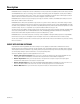
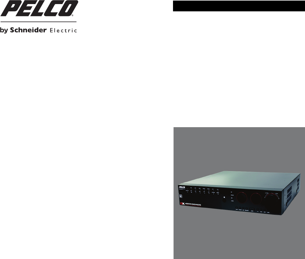
Description DX4700/DX4800 Series H.264 hybrid video recorders (HVRs) bring a new range of performance and capability to the Pelco DX Series product line. The DX4700/DX4800 Series offers a cost-effective solution to expand existing analog systems with megapixel IP recording. And, the ability to support two Pelco megapixel IP cameras or Axis® cameras, gives new power and flexibility in IP migration.
Product Overview APPLICATION WINDOW This section describes the DX4700/DX4800 application window, GUI toolbar, Setup menu, PTZ control, and on-screen keyboard. This manual describes how to operate and administer the unit using the mouse. NOTE: For a description of the remote control and front panel, refer to the DX4700/DX4800 Series Installation manual.
GUI TOOLBAR The GUI toolbar is used to access the Setup menu and controls that allow you to operate and configure the HVR. You can use the mouse to easily and quickly change settings and to operate the system. Figure 2. GUI Toolbar Status: Displays the current date and time. Setup: Displays the Camera, Record, Display, Linking, Network, and System menus. Search: Opens the Search menu to select the following search modes: Date/Time, Event Search, and Bookmark Search.
PTZ CONTROL The PTZ control is available for cameras that support PTZ functions using Pelco C, Pelco P, and Pelco D protocols. It is also available for supported third-party dome cameras. NOTE: When operating third-party cameras, the PTZ control supports the up, down, left, right, zoom in, and zoom out functions. Figure 3. PTZ Control Exit: Closes the PTZ control. Move: Pans and tilts the camera in the direction of the selected arrow. Speed: Selects the PTZ speed. ZOOM: Zooms the camera in and out.
ON-SCREEN KEYBOARD The unit provides an on-screen keyboard to perform the following functions: • Select a user name and type a password to log on to the unit • Create camera names • Create holiday schedule names • Assign TCP/IP settings (IP address, subnet mask, and so forth) • Set up mail accounts • Assign emergency agent IP addresses • Create user accounts DX4700/DX4800 on-screen keyboards operate similarly but display differently based on the task being performed.
Operation WARNING: Before you use the unit to record video, refer to Figure 5 and read the HDD partition notification. Figure 5. Camera Page and Partitioning Notification UNIT STARTUP To start the unit, on the front panel, press and hold the power button window will appear. until your hear a beep. After a few seconds, the unit’s application LOGGING ON AND LOGGING OFF You must log on to the unit with a valid user name and password to operate the HVR. User names and passwords are case sensitive.
UNIT SHUTDOWN NOTE: You must be logged on to the unit with administrator-level permission to shut down. To shut down the unit: 1. On the front panel, press and hold the power button 25 seconds to type the password before it closes. until you hear a beep. The Login virtual keyboard appears. You have approximately 2. Type the password. 3. Click OK. ABOUT BASIC SYSTEM DEFAULTS The unit comes preconfigured with system defaults that allow the HVR to be used to immediately view and record video.
MOTION AREA SELECTION The motion area is configured through the application window. Use the outline tool to draw a boundary around multiple areas. Selecting a Motion Area To select a motion area: 1. From the Linking menu, click Motion. 2. Click the Channel box, and select the channel you want to configure. 3. Configure the remaining settings. 4. In the Area window, drag the outline over an area from left to right (refer to Figure 6). The selected cells are highlighted in green. Figure 6.
INSTANT RECORDING AND PLAYBACK The instant recording feature allows you to start a manual recording session immediately from the live view mode. You can also initiate the instant recording mode for channels that are scheduled for normal, alarm, motion, or ATM/POS recording. Instant recording is the highest priority recording event. Observe the following instant recording conditions: • Instant (or normal) recording cannot start if the following conditions exist: – Video loss is displayed for the channel.
To start an instant playback: 1. From the application window, click a camera pane. A white border highlights the selected pane. 2. To start instant playback, click the play button . Figure 8. Instant Playback View PTZ IN LIVE VIEW The HVR displays a control for operating PTZ cameras that support PTZ functions using Pelco C, Pelco P, and Pelco D protocols. PTZ control is also available for supported third-party dome cameras. The PTZ option must be configured for each camera channel.
ACTIVATING PRESETS 1. Click a camera pane. 2. On the toolbar, click PTZ . The PTZ control is displayed. Figure 9. PTZ Operation 3. Click the number pad on the PTZ control, and then click PRESET. The camera moves to the preset location. ACTIVATING PATTERNS A pattern is a user-defined, viewable camera path with a specified beginning and end. Patterns are made up of a sequence of standard pan/tilt and lens commands. Patterns are stored in the internal memory of the PTZ device that is connected to the HVR.
PTZ PRESETS A preset is a user-defined camera position that uses PTZ and focus commands. (The camera’s autofocus option must be turned off to use presets.) The unit’s preset range is 0 to 255. For information about the number of presets supported by a given camera, refer to the documentation supplied with the camera. Programming a Preset 1. Click a camera pane, and then click PTZ 2. Click the Move . , ZOOM, and FOCUS buttons to position, zoom, and focus the camera. 3.
PTZ PATTERNS Programming a Pattern 1. Click SET. The camera is now in the programming mode. 2. Click a number representing the pattern (1 to 4). 3. Click PATTERN. 4. Move the camera through a series of movements using the on-screen PTZ and focus controls. a. Click the Move buttons . b. Click ZOOM, and then click FOCUS. 5. When you have finished programming the pattern, click PATTERN, and then click SET. 6. To verify that the pattern can be activated, click the pattern number, and then click PATTERN.
ACKNOWLEDGING AN ALARM OR MOTION EVENT The unit allows you to manually acknowledge an event state that has activated a relay output. By default, the HVR’s output relay is turned off when the post-alarm time expires. Acknowledging an alarm or motion event does not end alarm or motion event recording. The post-alarm time determines the time period for alarm recording. For information about configuring the relay off setting, refer to Output on page 54.
SPOT MONITOR The spot monitor allows you to monitor live and playback video. To select a division: 1. Click the Spot monitor icon SPOT . 2. Click a division. 3. Click OK. Figure 11. Selecting a Spot Monitor Division To view all channels in the sequence mode: 1. Click the Main monitor icon 2. Click the Sequence button . MAIN . 3. Click a division. 4. Click OK. For information about configuring the spot monitor, refer to Spot Monitor on page 21.
SYSTEM INFORMATION The System Information option displays system and hard disk information. To view all system information, you must be logged on to the unit. To view system information, click Information icon . The System Information screen displays all system information. Figure 13. Viewing System Information: Full Details Use the Pelco serial number when corresponding with Pelco about your unit. The MAC address is an internal number.
SEARCH VIDEO The search feature allows you to use the date/time, event, and bookmark search feature to find and play back video stored to the unit. You can use the date/time and event search features to view backed up video stored on a USB or CD/DVD media. To display the search menu, click the Search icon . The Search menu appears. Date/Time search is selected by default. Figure 14.
DATE/TIME SEARCH AND PLAYBACK You can search video data based on a calendar date (month, day, and year) and the time of day. For information about searching and playing back video recorded during daylight saving time (DST) 1:00 a.m. to 2:00 a.m., refer to DST Date/Time Search and Playback on page 25. 1. From the Search menu, click Date/Time. 2. Click the Target Device box, and select a media. 3. To enter the search date: a. Click the Calendar icon . The calendar appears. b.
DST DATE/TIME SEARCH AND PLAYBACK If the unit is configured for Daylight Saving Time (DST), the HVR uses a different approach to store and display video. When DST ends, the HVR’s internal time automatically adjusts backward one hour. Video is time-stamped and recorded one hour before and one hour after the time change. When DST begins, the HVR’s internal time automatically adjusts forward one hour and the unit records normally.
EVENT SEARCH To conduct an event search: 1. From the Search menu, click Event. 2. To enter the event search settings: a. Click the Target Device box, and then select a device. b. Click the Calendar icon . c. Click the year, month, and day of the week to define your event search date. d. Click OK e. Click the Time box, and then select a time. f. Click the Channel box, and select one or more channels. g. Click the Event Type box, and select an event. 3. Click Search. 4.
Bookmarking Playback Video 1. On the toolbar, click the Search Icon . 2. From the Search menu, select a search method. • Date/Time Search: Refer to Date/Time Search and Playback on page 24. • Event Search: Refer to Event Search on page 26. 3. Click Play. 4. Click the Bookmark icon 5. Click the Stop icon to bookmark a scene. to stop playback. Searching and Playing Back Bookmarked Video 1. From the Search menu, click Bookmark. The Bookmark dialog box appears.
ATM/POS SEARCH The ATM/POS search feature allows you to search recorded text data for a specific text string. ATM/POS search supports searching data backed up to an internal or external HDD. Table A describes the supported comparison search symbols. Up to ten different search options can be configured. Table A.
5. Click an event, and then click Play. The ATM/POS playback video appears in the window. Figure 22. ATM/POS Search Results 6. Click the Stop icon to stop playback. EXPORT SEARCH The Export search feature allows you to search video exported to USB or CD/DVD media. NOTES: • The unit supports the play , pause , and stop forward, end playback controls are not supported. buttons when playing back exported video.
4. Select an entry, and then click Play. Video is played back in the 1 x 1 view. Figure 24. Playing Back Exported Video 5. Click the Stop icon 30 to stop playback.
FORMATTING MEDIA AND EXPORTING VIDEO The unit allows you to export data to CD/DVD or USB media. You can view and playback the exported video on the unit or at the remote client computer. NOTES: • The erase and format features allow you to format media for use with the HVR. Although media can be formatted on a PC, Pelco recommends that you format the media on the HVR to guarantee functionality. For information about formatting media, refer to Erase Media on page 69.
CAPTURING A VIDEO SCENE The unit allows you to pause video playback to take a snapshot of a video scene. The image is saved to the USB device in JPEG format. To take a snapshot of a video scene: 1. Insert a USB device. 2. Click a camera pane. 3. Click the Playback button . Playback video appears. 4. Click Pause. 5. Click the Snapshot button . The Target Device message appears. 6. Click OK. The file is saved to the USB device.
Configuration NOTE: The DX4700/DX4800 is preconfigured for immediate operation. For a list of system defaults, refer to Appendix J: Factory Defaults on page 83. Only administrator-level users can configure the HVR. The Setup menu allows you to access the Camera, Schedule, Display, Linking, Network, and System menus to configure the DX4104 for your specific application requirements (refer to Figure 26). You must be logged on with administrator-level permission to configure the unit.
CAMERA MENU Figure 27. Camera Menu The unit allows you to configure the following settings: • Channel (Ch): Lists the input channels (CH 01 to CH 16, IP1, IP2). • Name: Allows you to create a unique name for each camera (CH 01 to CH 16, IP 01, IP 02). • Audio: Associates the audio input with the selected channel. • Disable: Allows a camera to be enabled or disabled from displaying video. To configure the camera settings: 1. From the Camera menu, click the Camera submenu. 2.
PTZ The DX4700/DX4800 supports up to 16 serial PTZ cameras. Multiple PTZ cameras can be connected and controlled individually by daisy-chaining the camera connections. The unit also allows you to assign each camera a PTZ control address. The unit allows you to configure the following settings: • Channel: Selects the channel (CH 01 to CH 16) for PTZ configuration. • Port: Sets the communication port for the camera: NONE, DATA1, DATA2, or COAXITRON.
IP CAMERA The DX4700/DX4800 supports up to two IP cameras. For information about the supported IP camera resolutions, refer to Appendix D: Supported IP Camera Resolutions on page 74. NOTES: • The unit does not support alarm or motion recording for IP cameras. • IP cameras only record in the normal recording mode. The unit allows you to configure the following settings: • Channel (Ch): Lists the IP network channels (IP 01 and IP 02).
To test the IP camera for operation: 1. From the Camera menu, click the IP Camera submenu. 2. Click the Channel box, and select an IP camera. 3. Click Test. A message appears confirming that the IP camera is configured correctly. 4. (Optional) If a test failed messages appears, resolve the configuration issue and repeat this procedure. 5. Repeat the previous steps (as necessary) to test the other IP camera. 6. Click Close. 7. Click OK. ATM/POS ATM/POS recording is only available for one channel at a time.
STORAGE The unit allows you to configure how internal hard disk storage is allocated for storing recorded video. The HVR combines the storage space of multiple HDDs into one logical disk and creates two partitions: TEMP and DATA. The system allocates 6 GB of disk space to the TEMP partition; the remaining space is allocated to the DATA partition. When the HDDs are formatted, the system creates two folders (Normal and Event) based on the Event Partition settings.
To format the drives: 1. From the Camera menu, click the Storage submenu. 2. Click Format. The on-screen keyboard appears. 3. Type Yes to format the HDD. 4. Click OK. 5. Wait while the system drives are formatted. After the format process is complete, the “Restart the System” dialog box appears. 6. Click OK. The unit restarts. SCHEDULE MENU The scheduling feature allows you to create daily, weekly, and holiday schedules for each channel. Up to 10 different holiday schedules can be created.
DAILY RECORDING SCHEDULE Figure 30. Daily Recording Schedule 1. From the Schedule menu, click the Schedule submenu. 2. Click a cell to set the ending time. 3. Continue to click the cell to select a new recording mode. 4. Repeat the previous steps (as necessary) to configure the recording mode for each channel. 5. Click Close. 6. Click OK.
Copying By Weekday, Weekend, and Day 1. From the Schedule submenu, click the day you want to copy. (In Figure 31, Wednesday is the selected schedule day.) Figure 31. Copying a Schedule by Week Day 2. Click Day Copy. 3. Right- or left-click the settings box to select a copying period: Weekday, Weekend, or Day. 4. Click OK. 5. Click Close. Copying By Channel 1. From the Schedule menu, click the day you want to copy. 2. Click a channel. 3. Click “Ch Copy” (channel copy). 4. Click each destination channel.
HOLIDAY SCHEDULES The unit supports up to 10 holiday schedules. When a holiday and a weekday schedule occur on the same date, the holiday schedule overrides the weekday schedule. Creating a Holiday Schedule 1. From the Schedule submenu, click the Holiday button. 2. Click Add. The Calendar appears. 3. Click a date. Figure 33. Creating a Holiday Schedule 4. Click OK. The on-screen keyboard appears. 5. Type the schedule name. Figure 34. Naming a Holiday Schedule 6. Click OK. The schedule appears.
7. Create a recording schedule for the channels. Figure 35. Creating a Holiday Recording Schedule 8. Click Close. 9. Click OK. Editing a Holiday Schedule 1. From the Schedule submenu, click the Holiday button. 2. Click List. 3. Select a holiday recording schedule, and then click Edit. Figure 36.
4. Edit the holiday recording schedule settings for the desired channel. Figure 37. Editing a Holiday Recording Schedule 5. Click Close. 6. Click OK. Deleting a Holiday Schedule 1. From the Schedule submenu, click the Holiday button. 2. Click List. 3. Select a holiday recording schedule, and then click Delete. 4. Click Close. NORMAL RECORDING NOTE: IP cameras only record in the normal recording mode.
ALARM RECORDING You can configure each camera to record at a different resolution, quality, and frame rate to capture alarm-triggered video. The unit also allows you to configure the prealarm and postalarm settings for each camera. Refer to Schedule Menu on page 39 for more information. You must configure the respective camera for alarm recording before the unit will respond to an alarm event. Refer to Schedule Menu on page 39 for more information.
TEXT RECORDING ATM/POS recording is only available for one channel at a time. In addition to configuring the text recording mode feature, there are other settings that must be configured. The associated features required to implement ATM/POS text recording mode are as follows: • Schedule menu: Allows you to schedule the ATM/POS camera channel for text recording and configure the ATM/POS camera’s text record settings (resolution, quality, frame rate, prealarm, and postalarm).
To configure the instant recording mode: 1. From the Camera menu, click the Instant/Panic Recording submenu. 2. Click the Ch 1 Resolution box, and enter a setting. 3. Configure the remaining settings for Ch 1. 4. Repeat the previous steps (as necessary) to configure additional channels. 5. Click Close. 6. Click OK. DISPLAY MENU Figure 38. Display Menu OSD (ON-SCREEN DISPLAY) The unit allows you to configure the following settings: • Channel Name: When selected, displays the channel name.
SEQUENCE You can set the sequence dwell time for the main and spot monitor in increments of 2, 5, 10, 20, 30, 40, 50, 60, 70, 80, or 90 seconds. To set the dwell time: 1. From the Display menu, click the Sequence submenu. 2. Click the Main Dwell Time box, and select the main monitor dwell time. 3. Click the Spot Dwell Time box, and select the spot monitor dwell time. 4. Click Close. 5. Click OK. For information about setting the spot monitor event pop-up, refer to Linking Menu on page 49.
LINKING MENU The Linking menu allows you to configure alarm inputs, motion inputs, and relay outputs. NOTES: • The prealarm and postalarm recording settings are configured in the normal recording option on the Camera menu. Refer to Schedule Menu on page 39 for more information. • The unit does not support alarm or motion recording for IP cameras. • ATM/POS recording does not end as configured by the postalarm setting. ATM/POS recording ends approximately 10 minutes after the postalarm time has ended.
To configure the alarm input channels: 1. From the Setup menu, click the Linking submenu. 2. Click Alarm. 3. Click the Input Type box, and select the alarm state. 4. Click the Camera box, and select the desired channel. 5. Configure the remaining settings. 6. Repeat the previous steps (as necessary) to configure additional channels. 7. Click Close. 8. Click OK. MOTION The unit allows you to configure the following settings: • Channel: Selects the motion channel (CH 01 to CH 16) for configuration.
ATM/POS DATA FORMAT The unit allows you to configure the following settings: • Input Channel: Allows you to select the camera channel associated with the ATM/POS data input. • Transaction Start: Allows you to enter a text string that starts the recording of data and video. For more information about ATM/POS text strings, refer to the documentation supplied with your particular unit. • Transaction End: Allows you to enter a text string that signals the end of the ATM/POS transaction.
NOTIFICATION The unit allows you to configure the following settings: • Alarm On: Sends a text-based alarm notification in response to an alarm event. • Motion Detection: Sends a text-based motion notification in response to a motion event. • Text In: Sends a text-based text notification in response to a text event. • Admin Password Changed: Sends an administrator 01 ID notification in response to a change to the 01 ID administrator password.
To configure the mail feature: 1. From the Linking menu, click the Mail submenu. 2. Click the Notification box. The remaining boxes become available. 3. Configure the remaining settings. 4. Click SMTP Test to verify the SMTP server connection. A pass or fail message appears and a test e-mail message is sent to each e-mail address. The “Test email sent successfully” message indicates a successful SMTP server configuration. Verify that each addressee received the test e-mail message. Figure 40.
To configure emergency notification: 1. From the Linking menu, click the Emergency submenu. 2. Click the Notification box. The remaining boxes become available. 3. Configure the remaining settings. 4. Click Close. 5. Click OK. OUTPUT You can configure how the relay output is controlled: alarm acknowledge or post-alarm time. The Relay Off setting does not control the actual alarm recording function. Turning off the relay output does not terminate the alarm recording mode.
USER MENU The DX4700/DX4800 features are organized into six categories: setup, search/play, export, PTZ, power off, and instant record. To operate the unit, a user must be assigned access rights to one or more of these categories. The User menu allows the administrator-level user the ability to quickly set up user groups. Each group can be configured to have access rights to one or more categories. Users can then be assigned to a specific group.
USER The unit allows you to configure the following settings: • User ID: Allows you to select the following: – ADMINISTRATOR: Allows you to change the default password and configure the administrator for automatic logout. The user name and group cannot be changed. – Group 01 to 08: Allows the assigned user access to the group’s categories. • User Name: Allows the administrator to create a user name for the person being authorized to access the unit.
SYSTEM MENU Figure 42. System Menu PROPERTIES The unit allows you to configure the following settings: • HVR Name: Enter a name for the unit up to 20 characters long. • Language: Select a display language. • Button Beep: When selected, a sound is produced when you press a button on the front panel or remote control. • Video Format: Selects NTSC or PAL. Changing the video format will initiate reformatting of the HDD. A confirmation dialog box appears prompting you to continue the reformat process.
Video Format WARNING: If you change the video format, the unit will delete all existing data, reformat the HDD, and restart. To change the unit’s video format: 1. From the System menu, click the Properties submenu. 2. Click the Video Format box, and then select a setting. The default video format is NTSC. Figure 43. Changing Video Format Message 3. To continue the reformatting process, click OK. A confirmation message appears after the process is complete. 4. Click OK, and then press Enter.
Factory Default To return the unit to its factory default settings: 1. From the System menu, click the Properties submenu. 2. Click Factory Default. A confirmation dialog box appears. 3. To continue the factory default reset process, click OK. 4. Click Close. 5. Click OK. NETWORK By default, the unit is configured to use Dynamic Host Configuration Protocol (DHCP). If a DHCP server does not reside on your network, the unit allows you to use a static IP address.
NETWORK STREAMING The unit allows you to configure the following settings: • Ch: Displays the channel number. • Resolution: Selects the recording resolution. For information about the supported recording resolutions, refer to Appendix E: Resolutions and Frame Rates (250 GB HDD) on page 75. • Quality: Selects the recording picture quality. • Frame Rate: Selects the frame rate. The frame rate is the number of transportable frames per second. According to resolution, the frame rate is set automatically.
DATE/TIME The unit allows you to configure the following settings: • Date: Sets the date and establishes the HVR’s internal calendar for all recorded video. • Time: Sets the system time and establishes the time for all recorded video. • Date Format: Sets the date format for displayed and recorded video. Selections include MM/DD/YYYY, DD/MM/YYYY, and YYYY/MM/DD. • Time Format: Sets the time format for displayed and recorded video. Selections include 12- and 24-hour time format.
To configure the unit to use a public NTP server: 1. From the System menu, click the NTP submenu. 2. Click the NTP box. The remaining boxes become available. 3. Click the Server box, and select PUBLIC SERVER. 4. To set the synchronization period, click the Sync. Interval box, and then select a setting. 5. Click NTP Test to verify your settings. 6. Click Close. 7. Click OK.
UPDATE The update feature allows you to upgrade HVR software. The current HVR configuration settings are not deleted or replaced during the update process. You can perform an update from either a local or a network location. The unit allows you to configure the following settings: • Method: Allows you update the software from a local or network location. If NETWORK is selected, the FTP server’s IP address must be provided. • Device: Allows you to updated the software from a DVD or USB device.
Updating Over the Network To update over the network: 1. From the System menu, click the Update submenu. 2. Click the Selection box, and then select a setting. 3. Click the Method box, and then select NETWORK. 4. Click the Update Server box, and then type the update server IP address. 5. Click Update and click OK. 6. Wait while the system searches for the update server and starts the update process. After the update process is complete, the “Restart the System” dialog box appears. 7.
BACKUP The backup feature allows you to perform an instant backup of recorded data. It also allows you to configure the system to perform an automatic backup of data on a scheduled basis. You must have administrator permissions for setting up and conducting backup procedures. The backup feature allows you to schedule how the HVR backs up recorded video data.
Instant Backup The instant backup feature allows you to manually back up data. The backup settings unique to the instant backup mode are as follows: • Schedule Start: Unavailable and is not used. • Time Range Date: Sets the date of the backup process. • Time Range Start: Sets the starting time (in hours and minutes) within the recorded database where the backup process begins. • Time Range End: Sets the ending time (in hours and minutes) within the recorded database where the backup process ends.
Daily Backup Schedule The daily backup feature allows you to perform an automatic backup of recorded data to a USB device. You can configure the time when the backup process starts and ends. The start and end times can be specified, and the HVR can be configured to back up all, normal (instant and normal recorded video), or event-initiated (alarm and motion) recorded video. The daily backup settings are as follows: • Device: USB media. • Schedule: Daily.
Weekly Backup Schedule The weekly backup feature allows you to perform an automatic backup of the current week’s data to a USB device only. The week begins at 00:00 hours on Monday and ends at 23:59 hours on Sunday. Data can be backed up for one or more days and from one minute to 24 hours. The unit can be configured to back up all, normal (instant and normal recorded video), or event-initiated (alarm and motion) recorded video. The weekly backup settings are as follows: • Device: USB device.
Erase Media The erase media feature allows you to erase and format media for use with the HVR. Although media can be formatted on a PC, Pelco recommends that the media be formatted on the HVR to ensure optimal equipment function. The HVR does not support a weekly or daily backup to CD/DVD media. If you try to format a CD or DVD when the unit is configured for a weekly or daily backup, a warning message appears. For information about supported media, refer to Appendix B: Supported Media Devices on page 72.
Appendixes APPENDIX A: OVERVIEW OF DX4700/DX4800 SETUP WINDOW AND OPERATING INFORMATION The unit can be operated and configured using the front panel, remote control, or mouse. This section describes using the mouse to operate and configure the unit. To access the Setup window, on the toolbar, click the Setup icon access the menu commands, click a command. . The Setup window appears and the Camera submenu is highlighted.
Table B. Setup Window Overview and Operation Information Pane Menu: Displays the menu options. Submenu: Displays the submenu options. Front Panel/Remote Control • Press the MENU/ESC button to move to the menu pane. • Press the up/down arrow buttons • Press ENTER to select an option. When a menu option is selected, the cursor moves to the first submenu option in the pane for the selected menu. • Press the up/down arrow buttons option. • Press ENTER to select an option.
APPENDIX B: SUPPORTED MEDIA DEVICES Table C. Supported Media Devices Media Guideline 72 CD±R CD±RW DVD±R DVD±RW USB Memory USB HDD Media can be formatted. No Yes No Yes Yes Yes Media can be formatted on a PC using the FAT32 file system. This media may or may not work in the HVR; therefore, Pelco recommends formatting the media on the HVR. No Yes No Yes Yes Yes Media must be formatted on the DX4700/DX4800 Series before backing up or exporting data to the device.
APPENDIX C: SUPPORTED PTZ PROTOCOLS Table D.
APPENDIX D: SUPPORTED IP CAMERA RESOLUTIONS Table E. Supported IP Camera Resolutions HVR Format NTSC NTSC PAL PAL 74 Encoding Resolution Location of Displayed Video Type of Displayed Video H.264 320 x 240 352 x 240 360 x 240 640 x 480 704 x 240 704 x 480 720 x 240 720 x 480 DX4700/DX4800 server Live and playback video DX4700/DX4800 server Pelco logo H.
APPENDIX E: RESOLUTIONS AND FRAME RATES (250 GB HDD) Table F. Recording Time (1 of 3) Recording Time (Hours) Resolution (NTSC/PAL) 352 x 240 / 352 x 288 Quality Frames Per Second (NTSC/PAL) 8-Channel 16-Channel 8-Channel 16-Channel LOWEST 30/25 1022/800 838/683 511/40 461/368 15/12.5 1188/1142 947/917 594/571 527/509 10/8 1508/1416 1139/1086 754/708 649/615 7.
Table F. Recording Time (2 of 3) Recording Time (Hours) Resolution (NTSC/PAL) 704 x 240 / 704 x 288 Quality Frames Per Second (NTSC/PAL) 8-Channel 16-Channel 8-Channel 16-Channel LOWEST 30/25 563/425 502/389 281/212 265/203 15/12.5 764/602 657/533 382/301 353/283 10/8 899/771 753/661 449/385 410/356 7.
Table F. Recording Time (3 of 3) Recording Time (Hours) Resolution (NTSC/PAL) 704 x 480 / 704 x 576 Quality Frames Per Second (NTSC/PAL) 8-Channel 16-Channel 8-Channel 16-Channel LOWEST 30/25 302/236 84/224 151/118 146/115 15/12.5 430/337 394/315 215/169 206/163 10/8 470/435 427/398 235/217 224/208 7.
APPENDIX F: TROUBLESHOOTING If the following instructions fail to solve your problem, contact Pelco Product Support at 1-800-289-9100 (USA and Canada) or +1-559-292-1981 (international) for assistance. Be sure to have the serial number available when calling. Do not try to repair the unit yourself. Leave maintenance and repairs to qualified technical personnel only. Table G. Troubleshooting (1 of 2) Symptom Suggested Action Unit does not power on. • Verify that the power cord is securely connected.
Table G. Troubleshooting (2 of 2) Symptom Suggested Action Video image has a lot of screen noise. • Verify that the camera’s video output is free of noise. • Verify that the camera is operating properly by replacing it with a known, working camera. • Verify that the input cable from the camera is not damaged and is connected correctly to the unit. • Verify that the video cable between the camera and unit is the correct type of cable.
APPENDIX G: HARDWARE AND SOFTWARE UPGRADE POLICY Pelco’s representations regarding product features and performance are limited to those made in the specification sheet and product manuals at the time the product was manufactured. Pelco does not represent or warrant that any upgrades to product hardware or software will be made available in the future. When possible, Pelco will offer product upgrades to purchasers of its products.
APPENDIX H: RECOVERING THE ADMINISTRATOR PASSWORD 1. On the left side of the unit, locate and note the manufacturer’s serial number. 2. In the toolbar, locate and note the current date. 3. Contact Pelco Product Support to receive the administrator password: 4. Enter the password provided by Pelco Product Support: C4655M (2/11) a. On the toolbar, click Login b. Type the password. c. Click OK. . The on-screen keyboard appears.
APPENDIX I: WORKING WITH PTZ DEVICES USING THE KBD300A KEYBOARD You can use the Pelco KBD300A keyboard to operate and configure PTZ devices. For information about connecting and operating the KBD300A, refer to the KBD300USBKIT Installation manual. Table H. Supported KBD300A Keyboard Features Keyboard Function Corresponding DX4700/DX4800 Function Joystick Pan/Tilt/Zoom: • KBD300A SHIFT LED Off: – Controls the camera’s PTZ operation. – Twist the joystick clockwise to zoom in, counterclockwise to zoom out.
APPENDIX J: FACTORY DEFAULTS You can reset the HVR to its original factory settings by importing or exporting the configuration settings. Some options cannot be reset (date, time, daylight saving, time zone, and user password settings). • Configuration Import: Imports the HVRs configuration data from the USB memory stick. • Configuration Export: Exports the configuration data from this HVR to the USB memory stick.
Table I. Factory Default Settings (2 of 6) Menu Submenu Property Setting Factory Default Setting Schedule Schedule Sun to Sat, Holiday Sun, Alarm/Motion (A/M) Sun, A/M Normal Record Ch 1 to 16 (cannot be changed) 1 to 16 Resolution 352 x 240 (NTSC) / 352 x 288 (PAL) 352 x 240 Quality STANDARD STANDARD Frame Rate 7.5 (NTSC)/6.25 (PAL) 7.5 Ch 1 to 16 (cannot be changed) 1 to 16 Resolution 352 x 240 (NTSC) / 352 x 288 (PAL) 352 x 240 Quality STANDARD STANDARD Frame Rate 7.
Table I. Factory Default Settings (3 of 6) Menu Submenu Property Setting Factory Default Setting Linking Alarm In 1 to 16 (cannot be changed) 1 to 16 Input Type N.O.
Table I.
Table I. Factory Default Settings (5 of 6) Menu Submenu Property Setting Factory Default Setting System (continued) Network DHCP Selected Selected IP Address N/A* N/A Subnet Mask N/A* N/A Gateway N/A* N/A Primary DNS N/A* N/A Secondary DNS N/A* N/A TCP/IP Port 9001 9001 Web Server Port 80 80 Audio Port 9003 9003 Bandwidth Throttle 100 Mbps 100 Mbps Ch 1 to 16 (cannot be changed) 1 to 16 Quality STANDARD STANDARD Frame Rate 7.5 (NTSC)/6.25 (PAL) 7.
Table I.
APPENDIX K: TIME ZONE CONVERSION CHART To determine your time, add the standard, daylight saving, or summer time to the Universal Time (UT). Table J.
C4655M (2/11)
PRODUCT WARRANTY AND RETURN INFORMATION WARRANTY Pelco will repair or replace, without charge, any merchandise proved defective in material or workmanship for a period of one year after the date of shipment.
www.pelco.