® IOP08 Series Intercept® Camera and Lens Installation/ Operation Manual C1441M-D (1/98) Pelco • 3500 Pelco Way, Clovis • CA 93612-5699 USA • www.pelco.
CONTENTS Section Page 1.0 GENERAL3 1.1 IMPORTANT SAFEGUARDS AND WARNINGS ............................... 3 2.0 DESCRIPTION .......................................................................................... 4 2.1 MODELS ............................................................................................ 4 3.0 INSTALLATION .......................................................................................... 5 3.1 ADJUSTMENTS ..............................................................
1.0 GENERAL 1.1 IMPORTANT SAFEGUARDS AND WARNINGS Prior to installation and use of this product, the following WARNINGS should be observed. 1. Installation and servicing should only be done by Qualified Service Personnel and conform to all Local codes. 2. Unless the unit is specifically marked as a NEMA Type 3, 3R, 3S, 4, 4X, 6, or 6P enclosure, it is designed for indoor use only and it must not be installed where exposed to rain and moisture. 3. Only use replacement parts recommended by Pelco. 4.
2.0 DESCRIPTION The IOP08 Series of cameras and lenses is part of the IDS08 Intercept® Series of domes. The IDS08 Series is an integral system that includes a back box (BB08), dome drive (DD08), dome receiver/driver (DRD08), and imager/optics package (IOP08). For installation and operation instructions for the back box, refer to manual C456M-D; for the dome drive, refer to C416M-C; and for the dome receiver/driver, refer to manual C466M-E. 2.
3.0 INSTALLATION The camera and lens package are installed at the factory. 3.1 ADJUSTMENTS Your optics package comes from the factory adjusted for a broad range of lighting conditions. For this reason, you may find it necessary to adjust your optics package to tailor the picture to your specific viewing environment. The following adjustments can be made to the Pelco optics package.
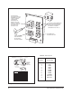
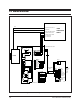
➤ Auto Iris Level is adjusted using a video meter to provide a video signal output of between 130 and 142 IRE (Institute of Radio Engineers; 1V p–p = 100 IRE’s) when lighting from skylights, low pressure sodium lights and fluorescent lights are present. ALC is adjusted to the midpoint between Peak and Average. The location for the controls of the above features, except for back focusing, are shown in Figures 2 and 3. Back focusing is addressed in Figure 1.
3.1.5 V-Phase (Vertical Phase) V-Phase (Vertical Phase) is valuable when multiple optic packages are switched by a sequential or matrix switcher. The vertical phase +/- buttons are used to compensate for vertical phase discrepancies which will occur in a multiple camera environment. In this type of environment, each cameras output is synchronized by the frequency of the power supply and phase. The “+” and “-” buttons referenced in Figure 2 can be used to obtain a synchronized picture.
V-PHASE BUTTONS (MOMENTARY PUSH-BUTTON) ADVANCE AND RETARD THE PHASE INTERVAL WITH RESPECT TO ZERO CROSSOVER OF AC LINE ±90° AGC (AUTOMATIC GAIN CONTROL) IS SET IN THE ON POSITION (SHOWN) AWB LOCK AWB ATW AGC OFF + V PHASE SHUTTER SHUTTER SPEED ADJUSTMENTS MAY BE PERFORMED BY USING A SMALL STANDARD SCREWDRIVER AND MOVING THE ROTARY SWITCH AS SHOWN. “0” POSITION IS FACTORY DEFAULT. SEE TABLE A FOR SETTING VALUES THIS MOMENTARY BUTTON LOCKS AWB Figure 2. Color Camera Adjustments Table A.
4.0 SERVICE CAUTION: Make certain not to drop or jar the camera/ lens combination or damage will result to the unit. WARNING: Ensure main electrical power is disabled by switching off the main power switch located under the trim ring up inside the back box. Should it become necessary to remove the camera/lens for service or replacement, follow the steps outlined below. Refer to Figure 4, if necessary. 1. Remove main electrical power by switching off main power switch located up inside the back box. 2.
5.
6.0 SPECIFICATIONS MECHANICAL Housing Construction: 0.050" aluminum Dimensions: 6.25" L x 4.25" H x 4.10" W (15.88 x 10.80 x 10.41 cm) ELECTRICAL Black/White (EIA) Camera Module Input Voltage: 24 VAC, 60 Hz Power Required: Less than 3 watts, plus auto iris of lens Video output: 1 V p–p, 75 ohms, negative sync Operating Temperature: 14° to 131°F (-10° to 55°C) Imaging Device: 1/2" CCD Illumination: 0.3 Lux @ f1.
7.0 WARRANTY AND RETURN INFORMATION WARRANTY Pelco will repair or replace, without charge, any merchandise proved defective in material or workmanship for a period of one year after the date of shipment. Exceptions to this warranty are as noted below: • Five years on FT/FR8000 Series fiber optic products. • Three years on Genex® Series products (multiplexers, server, and keyboard).