I N S T A L L A T I O N IS150 Series Camclosure® Integrated Camera System C3427M-D (2/09)
Contents Regulatory Notices . . . . . . . . . . . . . . . . . . . . . . . . . . . . . . . . . . . . . . . . . . . . . . . . . . . . . . . . . . . . . . . . . . . . . 5 Description . . . . . . . . . . . . . . . . . . . . . . . . . . . . . . . . . . . . . . . . . . . . . . . . . . . . . . . . . . . . . . . . . . . . . . . . . . . 6 Models . . . . . . . . . . . . . . . . . . . . . . . . . . . . . . . . . . . . . . . . . . . . . . . . . . . . . . . . . . . . . . . . . . . . . . . . . 6 Parts List. . . . . . . .
List of Illustrations 1 2 3 4 5 6 7 8 9 10 11 12 13 14 15 16 17 Package Components . . . . . . . . . . . . . . . . . . . . . . . . . . . . . . . . . . . . . . . . . . . . . . . . . . . . . . . . . . . . . . 8 Ceiling/Wall Installation . . . . . . . . . . . . . . . . . . . . . . . . . . . . . . . . . . . . . . . . . . . . . . . . . . . . . . . . . . . 9 Ceiling Tile Installation. . . . . . . . . . . . . . . . . . . . . . . . . . . . . . . . . . . . . . . . . . . . . . . . . . . . . . . . . . . .
Regulatory Notices This device complies with Part 15 of the FCC Rules. Operation is subject to the following two conditions: (1) this device may not cause harmful interference, and (2) this device must accept any interference received, including interference that may cause undesired operation. RADIO AND TELEVISION INTERFERENCE This equipment has been tested and found to comply with the limits of a Class B digital device, pursuant to part 15 of the FCC rules.
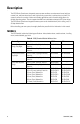
Description The IS150 Series Camclosure® integrated camera system combines an environmental cover, back box, camera, lens, and lower dome into a small, high-security system that is quick and easy to install. The system is perfect for a variety of indoor and outdoor applications and its versatile design allows for multiple mounting options. The unit supports both BNC and unshielded twisted pair (UTP) video wiring.
Indoor/outdoor dome, vandal resistant, in-ceiling mount, clear bubble, liner, gray finish Table B. IS151, Clear Bubble with Liner Camera Type Color, Wide Dynamic Range, Day/Night Color, High Resolution, Day/Night Color, Wide Dynamic Range Color, High Resolution Lens/Iris 3.0 to 9.5 mm, Day/Night Varifocal, Auto Iris 9.0 to 22 mm, Day/Night Varifocal, Auto Iris 3.0 to 9.5 mm, Day/Night Varifocal, Auto Iris 9.0 to 22.0 mm, Day/Night Varifocal, Auto Iris 3.0 to 9.5 mm, Varifocal, Auto Iris 9.0 to 22.
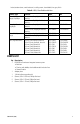
SHIPPING BOX CAMERA MODULE 1 EA. TRIM RING AND SMOKED BUBBLE 1 EA. BACK BOX 1 EA. < OR > ADAPTER PLATE 1 EA. TRIM RING, LINER, AND CLEAR BUBBLE 1 EA. 1/8-INCH HOLLOW SCREWDRIVER BIT 1 EA. SHOWN ACTUAL SIZE 8-32 X 0.375-INCH PHILLIPS FLAT HEAD SCREWS 4 EA. 8-32 X 0.75-INCH PHILLIPS FLAT HEAD SCREWS 2 EA. 8-32 X 1.25-INCH PHILLIPS FLAT HEAD SCREWS 4 EA. Figure 1.
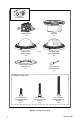
Cover and Back Box Installation The IS150 Series Camclosure integrated camera system mounts only into a wall or ceiling. UNSHIELDED TWISTED PAIR (UTP) VIDEO The IS150 Series offers support for unshielded twisted pair (UTP). The UTP video output signal is 1 Vp-p differential into a 100-ohm load. At a minimum, UTP requires Cat5, 100-ohm twisted pair cable. FIXED CEILING/WALL NOTE: You should install the camera module into the back box before installing the back box into the surface.
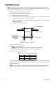
SUSPENDED CEILING NOTE: You should install the camera module into the back box before installing the back box into the surface. When installing the back box into the surface, rotate the camera module to access the mounting holes (refer to Camera Module on page 12 for more information). 1. Pull the video and power wires to the ceiling tile. 2. Mount the unit to the ceiling tile (refer to Figure 3): a. Remove the ceiling tile from the ceiling. b. Cut a hole 3.
4S DEEP ELECTRICAL BOX NOTE: You should install the camera module into the back box before installing the back box into the surface. When installing the back box into the surface, rotate the camera module to access the mounting holes (refer to Camera Module on page 12 for more information). 1. Attach the supplied adapter plate to the 4S box with two 8-32 x 0.75-inch Phillips flat head screws (supplied). 2. Pull the video and power wires to the ceiling tile. 3.
Camera Module The IS150 Series Camclosure camera module includes the camera, camera bracket, and heater board. To perform most camera adjustments, you must remove the module from the back box. Use the following instructions to remove and reinstall the camera module. WARNING: Heater elements could be hot! When camera power is on, use caution when adjusting the camera. This applies to all models. MODULE REMOVAL To remove the camera module from the back box: 1.
2. Unplug the camera (10-pin), service (3-pin), and heater board (4-pin) connectors from the back box (refer to Figure 6). SERVICE CONNECTOR CAMERA CONNECTOR HEATER BOARD CONNECTOR Figure 6.
CAMERA ORIENTATION At the factory, the camera module is configured for ceiling mounting. For wall mounting, you must change the camera orientation or the video image could be upside down or sideways. To change the camera orientation (refer to Figure 7): 1. Remove the camera module from the back box, if necessary. 2. Remove the tilt adjustment screw and lock washer from each side of the camera. 3. Carefully rotate the camera one quarter or one half turn, depending on the desired camera angle.
Camera Adjustments To perform the following camera adjustments, make sure to connect the camera and service connectors. You may have to remove the camera module from the back box. Connect a monitor. Then turn on power to the camera and monitor. To use the service connector, refer to Service Connector on page 27. To set the DIP switches, or to adjust the auto iris level (DN or CH) or the vertical phase (DW or CW), you will need a miniature trimpot adjustment tool with a 0.05-inch (1.27 mm) blade.
To adjust the focus: 1. Loosen the focus locking screw. 2. Position the inverted dome approximately 0.125 inch (3.175 mm) from the front of the lens. Make sure that the lens and the dome are centered (refer to Figure 9). 3. Turn the focus locking screw clockwise or counterclockwise to adjust the focus. 4. When the optimal focus is reached, tighten the focus locking screw ZOOM FOCUS 0.125 INCH (3.175 mm) CENTER BUBBLE WITH LENS Figure 9.
DN/CH SERIES ADJUSTMENTS Refer to Figure 10 to adjust the IS150-DN or IS150-CH model. Figure 10. Adjusting the IS150-DN/CH Series Camclosure SWITCH SETTINGS Locate the DIP switch. Then set the switches for your installation. SW4-1: Auto Gain Control The automatic gain control (AGC) adjusts the image automatically to compensate for changes in light levels. Set SW4-1 to ON to enable AGC. Set it to OFF to disable AGC. The default setting is ON.
SW4-4: Flickerless In certain lighting conditions, a flicker in the light source may affect camera operation. Flickering can be caused by a number of conditions, including the quality of the source power and the age and type of fluorescent bulbs and ballasts. Set SW4-4 to ON to enable flickerless operation. The camera will remove the effects of flickering when present. The shutter speed will be set to 1/120 (NTSC) or 1/100 (PAL). Set it to OFF to disable flickerless operation. This is the default setting.
VERTICAL PHASE ADJUSTMENT Use this procedure for 24 VAC operation only. When using more than one camera power supply, a brief vertical roll may occur on the monitor when switching from one camera to another. To eliminate vertical roll, reverse the 24 VAC connections on one camera. If both cameras are connected to the same transformer, this should solve the problem. If the problem persists, adjust the phase control by synchronizing, or line-locking, the cameras to one another.
DAY/NIGHT OPERATION NOTE: This section only applies to DN model cameras. DN model cameras regularly check the brightness level of the field of view to determine when to switch between day (color) and night (black-white) operation. Actual brightness threshold levels are affected by camera angle, amount of zoom, field of view, lens, and type of lighting. The switching process lasts from seven to 10 seconds. RISING LIGHT LEVEL COLOR MODE 1.5 lux B-W MODE COLOR MODE 3.
DW/CW SERIES (WIDE DYNAMIC RANGE) ADJUSTMENTS Refer to Figure 12 to adjust the IS150-DW or IS150-CW model. SW1 DEFAULT SWITCH POSITION R7 Figure 12. Adjusting the IS150-DW/CW Series Camclosure SWITCH SETTINGS Locate the DIP switch. Then set the switches for your installation. SW1-1: Video Format Set SW1-1 to ON for NTSC. Set it to OFF for PAL. The default setting is ON. SW1-2: Line Sync When multiple cameras are connected to the same switching device, vertical roll may occur on the monitor.
SW1-4: Auto White Balance/Manual White Balance Auto white balance (AWB) is enabled by default (ON). To manually set and lock the white balance: 1. Set SW1-4 to ON. 2. Hold a white background in front of the lens until the video shows all white. 3. While holding the background in place, set SW1-4 to OFF. A green block and a white block alternate briefly on the video image until the manual white balance (MWB) process is complete.
SW1-8: Day/Night Operation (DW models only) NOTE: On CW models, SW1-8 is unused and does not affect camera operation. DW model cameras regularly check the brightness level of the field of view to determine when to switch between day (color) and night (black-white) operation. Use SW1-8 to set the general light levels at which the camera will automatically switch. Set SW1-8 to ON (dark) to use standard thresholds to switch between color and black-white operation. This is the default.
AUTO IRIS LEVEL ADJUSTMENT The electronics of the IS150-DW and IS150-CW Series Camclosures automatically adjust the camera to the auto iris. Auto iris level adjustments are not necessary. VERTICAL PHASE ADJUSTMENT Use this procedure for 24 VAC operation only. When using more than one camera power supply, a brief vertical roll may occur on the monitor when switching from one camera to another. To eliminate vertical roll, reverse the 24 VAC connections on one camera.
Camera Positioning Rotate and tilt the camera module to position the camera. Then tighten the tilt screws (axis ì in Figure 14). NOTE: Do not over-rotate the module. Excessively turning the module in one direction could result in damage to the wiring. ì Tilt 80° (20° to 100°) î Pan 360° ï Rotation 360° Figure 14.
Install Liner and Trim Ring 1. Adjust the liner (if installed), refer to Figure 15: a. Align the screw holes in the trim ring with those in the back box to identify the proper liner position. b. Loosen the three Phillips screws located in the trim ring. c. Insert the blade of a standard screwdriver in one of the adjustment grooves. Rotate the liner to position the viewing window over the camera lens. d. Tighten the three Phillips screws to lock the liner in place.
Service Connector The IS150 Series Camclosure integrated camera system includes a service connector that outputs camera video. Use it at the installation site to set up the field of view and to focus the camera. SERVICE CONNECTOR Figure 16. Service Connector Pelco offers two optional items that plug directly into the service connector. Before using either option, you must loosen the tamper-resistant screws to remove the trim ring from the back box. Use the 1/8-inch hollow screwdriver bit (supplied).
To assemble the cable: 1. Attach the CPM 88 miniature coaxial connector to one end of the cable. Follow the directions supplied with the miniature coaxial connector. 2. Attach the 2.5 mm monaural plug to the other end of the coaxial cable (refer to Figure 17): a. Remove the support sleeve from the plug. b. Slip the support sleeve over the end of the cable. c. Prepare the cable. d. Solder the center connector of the cable to the center pin of the plug. e.
Specifications GENERAL Pan/Tilt Adjustment Pan Tilt Rotation Construction Finish Light Attenuation Smoked Clear Unit Weight ELECTRICAL Input Voltage* Synchronization Power Consumption Camera Heaters Manual 360° 80° (20° to 100° range) 360° Aluminum with steel camera mounting bracket and polycarbonate dome White polyester powder coat trim ring with gray polyester powder coat back box f/1.5 light loss Zero light loss 1.70 lb (0.
CAMERA/LENS If you need technical specifications for the camera itself, refer to the IS150 specification online at www.pelco.com. (Design and product specifications subject to change without notice.) 5.48 (13.92) 3.50 (8.89) 1.75 (4.45) 2.42 (6.15) 3.75 (9.53) NOTE: VALUES IN PARENTHESES ARE CENTIMETERS; ALL OTHERS ARE INCHES. REVISION HISTORY Manual # C3427M C3427M-A C3427M-B C3427M-C C3427M-D 30 Date 2/07 5/07 7/07 10/07 2/09 Comments Original version.
PRODUCT WARRANTY AND RETURN INFORMATION WARRANTY Pelco will repair or replace, without charge, any merchandise proved defective in material or workmanship for a period of one year after the date of shipment.
www.pelco.com Pelco, Inc.