I N S TA L L AT I O N / O P E R AT I O N CM6800E-48X8 ® Matrix Switcher/Controller C1528M-F (6/05)
CONTENTS Section Page IMPORTANT SAFEGUARDS AND WARNINGS .................................................................................................................................................................. 7 DESCRIPTION ..................................................................................................................................................................................................................... 8 MODELS ......................................................
OPERATION ........................................................................................................................................................................................................................ 65 OVERVIEW ................................................................................................................................................................................................................ 65 OPERATING THE CM6800E .......................................
LIST OF ILLUSTRATIONS Figure 1 2 3 4 5 6 7 8 9 10 11 12 13 14 15 16 17 18 19 20 21 22 23 24 25 26 27 28 29 30 31 32 33 34 35 36 37 38 39 40 41 42 43 44 45 46 47 48 49 50 51 52 53 54 55 56 57 58 4 Page Sample CM6800E-48X8 System ...................................................................................................................................................................... 8 Sample CM6800E 96 x 16 System ....................................................................................
9 60 61 62 63 64 65 66 67 68 CM9760-MGR Comms Page ............................................................................................................................................................................ 85 CM9760-MGR Cameras Page ......................................................................................................................................................................... 86 CM9760-MGR Link Cameras Page .........................................................
C1528M-F (6/05)
IMPORTANT SAFEGUARDS AND WARNINGS 1. Read, keep, and follow these instructions. 2. Heed all warnings. 3. There are no user-serviceable parts inside this unit. Only authorized service personnel may open the unit. 4. Installation and servicing should only be done by qualified service personnel and conform to all local codes. 5. WARNING: To reduce the risk of fire or electric shock, do not expose this unit to rain or moisture if this unit is designed for indoor use only. 6.
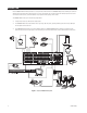
DESCRIPTION Pelco’s CM6800E Matrix Switcher/Controller is a cross-point video matrix switcher. The CM6800E-48X8 provides switching and control for 48 video inputs and eight monitor outputs from any one of up to 18 keyboards, PCs, and other devices. All 48 video inputs can be used to view video from other devices, such as multiplexers. Forty inputs allow for looping to other devices.
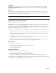
REL2064 (ADDITIONAL RELAYS) ALM2064 (ADDITIONAL ALARMS) CAMERA 48 ALARM 1 ALARM 8 CAMERA 96 CAMERA 1 ALARM 9 ALARM 16 CAMERA 49 PTZ CONTROL CM6800E-48X8 MAIN UNIT PTZ CONTROL CM6800E-48X8 EXPANSION UNIT DATA CABLE VIDEO RIBBON CABLE MONITOR 1 MONITOR 8 MONITOR 9 MONITOR 16 ALL KEYBOARDS CONNECT TO MAIN UNIT GENEX MULTIPLEXER Figure 2.
Programming The CM6800E features easy programming through on-screen menus or the Windows®-based CM6800-MGR software package. All programming is password-protected. Programming menus are provided in English, French, German, Italian, Polish, Portuguese, Russian, and Spanish. Keyboards Up to 16 keyboards from the KBD100/200A/300A Series and 2 keyboards from the KBD960/KBR960 Series can be connected to the CM6800E.
Alarm Inputs Eight internal alarm inputs are provided on the rear panel of the matrix switcher/controller. These internal alarm inputs are programmable to associate any camera to any input. A 96 x 16 system provides 16 internal alarm inputs (eight on each CM6800E-48X8 unit). Up to four ALM2064 Alarm Interface Units can be connected to the CM6800E (main unit only in a 96 x 16 system). Each alarm interface unit can handle up to 64 alarms.
MODELS CM6800E-48X8 Matrix switcher/controller with 48 video inputs and 8 monitor outputs, NTSC-configured, 120/230 V, 50/60 Hz, autoranging (UL; cUL; FCC, Class B) CM6800E-48X8-X Matrix switcher/controller with 48 video inputs and 8 monitor outputs, PAL-configured, 120/230 V, 50/60 Hz, autoranging (CE, Class B) CM6800-96X16 Expanded switcher/controller system; contains two CM6800E-48X8 units and one CM6800EKIT.
INSTALLATION Unpack and inspect all parts carefully. The following parts are supplied: 1 4 4 1 4 1 4 CM6800E Switcher/Controller 10-32 x .750-inch pan head screws .500” OD nylon washers Power cord 6-foot (1.8 m) straight data cables with RJ-45 connectors 6-foot (1.8 m) reversed data cable with RJ-45 connectors RJ-45 wall block terminals NOTE: There are no user-serviceable parts inside this unit. Only authorized service personnel may open the unit. MOUNTING 1. Select a suitable location for the CM6800E.
VIDEO SOURCES The CM6800E offers 48 full-function video inputs which support Coaxitron PTZ control and video loss detection. Forty video inputs, labeled 1 through 40, can be used for looping video connections with terminating and unterminating switches on the back panel. The eight alternate source inputs, labeled 41 through 48, are terminated inputs. They do not have loop-through connectors or selectable termination switches, but otherwise they offer the same functionality as video inputs 1 through 40.
2. On video inputs 1 through 40, set the terminating switches according to your system requirements. Video inputs 41 through 48 cannot be used for loop-through connections. Terminating switches are used to terminate or unterminate the video input. The factory default has the switches set in the terminated (75-ohm) position. If you are connecting only a camera to an input, leave the switch in the terminated position. Figure 7.
CONTROL LINES You cannot connect a Coaxitron camera to the PTZ-A or PTZ-B ports. If your video sources are all controlled by Coaxitron, skip this section. Connect camera control lines to receivers. If any of your video sources are using D or P protocol via RS-422 communications, they will connect at the PTZ-A and PTZ-B connectors on the back of the CM6800E. NOTE: D and P protocol receivers cannot be mixed on the same communication port but you can use D on one port and P on the other.
MONITORS The CM6800E supports eight monitors. 1. 2. 3. Install monitors according to the instructions provided with them. Connect the monitor cables at the appropriate video output BNC receptacles on the back of the CM6800E. Terminate cables at the monitors. If you are looping to other devices, terminate only at the last device.
ALARMS The CM6800E provides numerous alarm handling options. Refer to the Programming section for a detailed description. 1. Connect wires from the sensors to the respective alarm input points on the connectors at the back of the CM6800E. Each sensor requires two wires – one wire to the alarm input terminal and a return wire to one of the ground terminals on the connector. The CM6800E supports eight internal alarms. Alarm sensors can be either N.O. (normally open) or N.C. (normally closed) contacts.
CONNECTING DEVICES THROUGH THE COMMUNICATION PORTS The CM6800E Matrix Switcher/Controller provides eight communication ports on the rear panel for connecting peripheral components. Instructions are provided in this section for the most commonly used connections. NOTE: Connection instructions for other peripheral devices, such as the CM9760-MDA or CM9760-CDU-T, are provided as Pelco Technical Tips.
Table B. Communication Port Devices and Wiring (Continued) Port Input Type 7 RJ-45 Wiring RS-485 or RS-232 Pin-Outs RS-485 Pin-Outs: 1 Rx+ 2 Rx5 Ground 7 Tx8 Tx+ Default Device ASCII device Programmable to Other Device(s) CM9760-MDA, Satellite, keyboards (KBD100/200A/300A) ASCII device CM9760-MDA, keyboards (KBD100/200A/300A) RS-232 Pin-Outs: 1 Rx 5 Ground 8 Tx 8 RJ-45 RS-485 or RS-232 RS-485 Pin-Outs: 1 Rx+ 2 Rx5 Ground 7 Tx8 Tx+ RS-232 Pin-Outs: 1 Rx 5 Ground 8 Tx Table C.
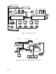
PC DB9 CONNECTION COM 1 PC SETUP (RS-232) USE DB9 CONNECTION OR ALTERNATE RJ-45 CONNECTION BOTH CANNOT BE USED SIMULTANEOUSLY RS-232 NULL MODEM CABLE NOTE: TOTAL NUMBER OF KBD100/200A/300A SERIES KEYBOARDS CONNECTED TO THE CM6800 CANNOT EXCEED 16 COM 5 & 6 LOCAL KEYBOARDS (RS-485) KBD100/200A/300A SERIES MAX # OF DEVICES = 8 010101 1 2 3 4 5 6 7 8 16 PC RJ-45 CONNECTION 1 5 2 6 CONTROL A T T + - COM 2 (RS232) BAY TO BAY CMM6800-48X8E OR ASCII CONTROL 31 32 2 3 4 6 7 8 3 7 4 8 R R
KBD100, KBD200A, AND KBD300A SERIES KEYBOARDS You can connect up to eight KBD100/200A/300A Series keyboards to any of the following ports: • • • • COM 5 (1 direct-powered keyboard or up to 8 remotely connected keyboards) COM 6 (1 direct-powered keyboard or up to 8 remotely connected keyboards) COM 7 (up to 8 remotely connected keyboards) COM 8 (up to 8 remotely connected keyboards) The total number of KBD100/200A/300A Series keyboards connected to the CM6800E cannot exceed 16.
3. Set the keyboard DIP switches for the desired address for the local keyboard (refer to Figure 12 and Table D). Table D. Keyboard Addresses: KBD100/200A/300A Series Keyboards Keyboard Address 1 2 3 4 5 6 7 8 0 1 2 3 4 5 6 7 1 OFF ON OFF ON OFF ON OFF ON Switch Settings 2 3 OFF OFF OFF OFF ON OFF ON OFF OFF ON OFF ON ON ON ON ON 4 OFF OFF OFF OFF OFF OFF OFF OFF Table E.
KBD100, KBD200A, and KBD300A: Remote Keyboards Use COM 5, 6, 7, or 8 for remote keyboard connections. Each port can support up to eight KBD100/200A/300A Series keyboards. Do not exceed a total capacity of 16 keyboards connected to the CM6800E. NOTE: A KBDKIT or KBDKIT-X is required to connect remote keyboards. The KBDKIT(-X) consists of two RJ-45 wall blocks and one transformer. Use one wall block for each keyboard.
M DEVICES (KBD960, ALM2064, REL2064) M protocol devices (KBD960/KBR960 keyboards, ALM2064 Alarm Interface Units, and REL2064 Relay Interface Units) can be connected to COM 3 on the CM6800E. If only one device is to be connected to COM 3, use the instructions for that device in the following sections. If more than one device is to be connected to COM 3, refer to the Multiple M Devices section. Connect M devices to the CM6800E with straight cables.
Connecting a Single KBD960/KBR960 Keyboard To connect a single KBD960/KBR960 Keyboard to the CM6800E: 1. 2. Connect the keyboard to the CM9505UPS using the straight cable supplied with the keyboard. Connect the CM9505UPS to COM 3 on the CM6800E using the 6-foot (1.8 m) straight data cable supplied with the CM6800E. NOTE: After completing system installation and power-up, you must configure the KBD960/KBR960 settings. Refer to the System Start-Up section.
Connecting a Single ALM2064 Alarm Interface Unit To connect a single ALM2064 Alarm Interface Unit: 1. Connect the ALM2064 OUT port to COM 3 on the CM6800E using the 6-foot (1.8 m) straight data cable supplied with the CM6800E. 2. Set SW2, DIP switches 1-8 to the appropriate positions for the local address (default address setting is 1). Refer to the ALM2064 Alarm Interface Unit Installation/Operation Manual for instructions.
Connecting a Single REL2064 Relay Interface Unit To connect a single REL2064 Relay Interface Unit: 1. Connect the REL2064 OUT port to COM 3 on the CM6800E using the 6-foot (1.8 m) straight data cable supplied with the CM6800E. 2. Set SW2, DIP switches 1-8 to the appropriate positions for the local address (default address setting is 1). Refer to the REL2064 Relay Interface Unit Installation/Operation Manual for instructions.
Multiple M Devices Multiple M devices (KBD960/KBR960, ALM2064, and REL2064) can be connected to COM 3 on the CM6800E, either as local devices or remote devices (when connecting two KBD960/KBR960 keyboards to the CM6800E, you must use a remote connection). Multiple M Devices: Local Connection 1. If you are connecting a KBD960/KBR960, connect it to the CM9505UPS with the straight cable supplied with the keyboard.
Multiple M Devices: Remote Connection Use a remote connection when the distance from the CM6800E is greater than 6-feet (1.8 m). 1. Connect each ALM2064 and REL2064 unit to a wall block with a 6-foot (1.8 m) straight cable (supplied with the CM6800E). You can connect a maximum of four ALM2064 units and four REL2064 units to the CM6800E. 2. If you are connecting a KBD960, connect it to the CM9505UPS with the straight cable supplied with the keyboard.
CONNECTING A PC The CM6800E provides PC-based setup and programming software that facilitates complete switcher programming and configuration. Refer to the CM6800-MGR Quick Start Guide for instructions on using the software. Connect a PC to the CM6800E to access the CM6800-MGR software or to download upgrades to the software. You can connect a PC to the CM6800E through either a DB9 port or an RJ-45 port. You cannot use both ports simultaneously. 1.
CONNECTING GENEX MULTIPLEXERS Use COM 4 to connect up to eight Genex Multiplexers to the CM6800E. 1. Connect the COM IN port of the multiplexer to COM 4 on the CM6800E, using the 6-foot (1.8 m) reversed data cable supplied with the CM6800E. One reversed cable and four straight cables are supplied with the CM6800E. Use the reversed cable for connecting the Genex multiplexer to the CM6800E. A straight data cable is supplied with the Genex multiplexer.
LOCAL AUXILIARIES The CM6800E provides three local auxiliary (AUX) outputs on the rear panel for controlling VCRs, printers, and other devices. These outputs can be activated directly from a keyboard by using the F1, F2, and F3 function keys, or they can be activated by an alarm (determined by programming). Both relay contacts and TTL outputs are used. In addition, you can connect up to four REL2064 Relay Interface Units to the CM6800E.
Connecting the Open Collector Output – F3 (TTL) F3 is a TTL open collector output. This output provides a path to ground to control the low voltage trigger input on many devices. It can control higher voltage control inputs via isolation relays. Refer to Figure 27 for wiring details. Do not exceed the voltage and current ratings for the TTL output. An external pull-up resistor is usually necessary. The formula for calculating the resistor value is given in Figure 26.
CONNECTING A 96 X 16 SYSTEM 1. Install each CM6800E-48X8 unit and connect appropriate devices to each unit. Note that the CM6800E-48X8 expansion unit must be installed within three feet of the CM6800E-48X8 main unit. NOTE: If you expand a 48 x 8 system to a 96 x 16 system, you must verify that each CM6800E-48X8 unit contains the same level of switcher software. Refer to Upgrade CM6800 Switcher Software in the Appendix.
SYSTEM START-UP After completing the system installation, follow the procedure below to start proper system operation. Skip any “system-specific” steps that do not apply to your system setup. POWER-UP THE SYSTEM Plug the CM6800E power cord into a 120/230V, 50/60 Hz power source. Plug in and turn on all devices connected to the CM6800E. Once the system is powered-up you will see video from camera 1 and the following time/date stamp on all system monitors: Figure 29.
CONFIGURE THE SYSTEM The CM6800E is shipped from the factory with default programming settings. If the defaults are acceptable, the CM6800E can be operated without any user programming. However, you may want to program the following basic system settings: • Time and date. • Camera titles: by default, each camera is titled “CAM #” (# = camera number). • Camera video source: Extended Coaxitron protocol receivers can be operated without any programming changes.
96 X 16 SYSTEM SETTINGS When you connect two CM6800E-48X8 units together in a 96 x 16 system, you must access the System programming screen and change the setting to 96 x 16. Refer to the Programming section for instructions. KBD960/KBR960 KEYBOARD Configure the KBD960/KBR960 settings. 1. Set DIP switch 2 to the ON position. 2. Enter Setup Mode. Set the local address (1-8). (Note: the baud rate is set by default to 19200.) Each M device connected to the CM6800E must have a unique local address.
MONITOR COLOR ADJUSTMENT: Once you have connected all devices and powered the system, use the CM6800E color bars as a reference tool for adjusting the color on each monitor. 1. Enter 9999. 2. Press the CAM key. Broadcast quality color bars appear on the monitor. 3. Adjust color on each monitor as necessary until the color bars match the following color order on the monitor (for black and white monitors you can use the color bars to adjust brightness): Figure 30.
PROGRAMMING THE CM6800E The CM6800E is shipped from the factory with default programming settings. If the defaults are acceptable, the CM6800E can be operated without any user programming. However, you may want to program the following basic system settings: • Time and date • Camera titles • PTZ control via hardwire data connections • Alarm contacts Alarms must be enabled before they are functional. • Access All access is set to YES by factory default.
CM6800E PROGRAMMING MODE 1. If you have not already done so, select the monitor (KBD960/KBR960: if the Camera menu appears, press 2. Press the PGM key (or select PGM to exit). on the KBD960/KBR960). The Password screen appears. Note that on the KBD960/KBR960 you must first select and DEF . Then enter the Define PIN (Default: 1234), and select MENU .
KBD100/200A/300A Keyboards To return to active video you can: To return to active video you can: • Press the PGM key once while in the Main Menu. • Select • Press the PGM key twice from anywhere else in the programming screens. • Navigate to the RETURN field and navigate left or right to return to the previous screen or menu. PGM once while in the Main Menu. • Select PGM twice from anywhere else in the programming screens.
Function Keyboard Scroll through options in programming fields. KBD100/200A/300A Use F1 and F2. Or (KBD300A only) use the joystick to navigate left or right. F1 F2 NOTE: The joystick does not scroll options in all fields. KBD960/KBR960 Select the or right. or icons or use the joystick to navigate left NOTE: The joystick does not scroll options in all fields. Select option in a programming field. All keyboards 1. Scroll through the options until the appropriate entry appears in the field. 2.
ACCESS The CM6800E supports the following ways to restrict switching system access: Keyboard to Monitor: Restrict a keyboard from accessing selected monitors. Camera to Keyboard: Restrict a keyboard from calling selected cameras to monitors. Or video viewing only: permit the viewing of selected cameras while preventing pan and tilt control. Camera to Monitor: Restrict the viewing of selected cameras on selected monitors. All system access is set to YES by default.
ALARM PROGRAMMING Alarmed cameras can be displayed on one or several monitors as part of one or several alarm groups (each monitor can display only one alarm group). Before programming alarm settings note the following precautions: • • Verify that no automated system functions are set to run, such as a macro that would arm or disarm an alarm. Ensure that system operators do not arm or disarm any alarms while you are programming alarm settings.
PROGRAM AN INTERNAL OR EXTERNAL ALARM CONTACT Use the Alarm Contact screens to configure alarm inputs. When an alarm is triggered, the logical alarm number, the alarm icon, and the alarm letter (“I” for internal; “E” for external) appear on monitors programmed through the Alarm Group screen to display the alarm.
3. In the STP matrix, configure up to eight steps to be triggered as a result of this alarm. a. In the CAM field select a camera (use the logical camera number) to be displayed on a system monitor. b. In the DWL field, enter the amount of time the camera view is displayed in an alarm sequence; enter a dwell time between 1 and 99 seconds. c.
PROGRAM A VIDEO LOSS ALARM Use the Video Loss screen to program the CM6800 to detect video loss from any camera input and indicate the loss through alarm mode – the logical alarm number, the alarm icon, and a “V” (for video loss) appear on system monitors as specified by alarm group assignment.
Assign a Logical Alarm Number (Optional) Each CM6800E alarm type (internal, external, and video loss) has been assigned a series of default logical alarm numbers, which start at 001 and continue sequentially. Depending on how you use the CM6800E system, the default logical alarm numbers could create a numbering conflict, as described below.
AUXILIARY OUTPUTS The three local auxiliary (AUX) outputs on the rear panel of the CM6800E can be operated manually from a system keyboard or automatically in response to an alarm.
CAMERA PROGRAMMING Extended Coaxitron protocol receivers can be operated without any programming changes, other than changing the camera title, if necessary. For other receiver control protocols, you must select the control type for the device connected to each video input. If necessary, first program logical camera number. PROGRAM LOGICAL NUMBERS Default logical numbers start at 0001 and continue sequentially to 0048 (or to 0096 in a 96 x 16 system).
PROGRAM CAMERAS PELCO SWITCHER MODEL CM6800E MAIN MENU 1 CAMERA 2 LOGICAL CAMERA 3 MONITOR 4 ACCESS 5 TIME & DATE 6 PORT 7 PRIORITY 8 SEQUENCE 9 MACRO 10 ALARM CONTACTS 11 EVENT TIMER 12 SET AUXILIARY 13 SET PASSWORD 14 SYSTEM 15 ABOUT CM6800E ENGLISH RETURN CAMERA 0001 VERTICAL DRIVE: OFF CONTROL: EXT COAX PORT ADDRESS: 01 CAMERA TITLE CAM 1 SELECT CHARACTER RETURN Figure 40. Program Cameras 1. In the CAMERA field, select the logical camera number of the video input to be defined. 2.
4. Select the camera title. This title (up to 20 characters) appears on the monitor during real-time camera display. a. Navigate to the position in the camera title that you want to change. b. Use F1 and F2 to scroll through the camera title characters; once you reach the desired character for that position, navigate to the next position. The default title characters are 26 upper case letters and the numbers 0-9.
EVENT TIMERS You can automate system operation to activate sequences or macros on specific monitors. Events can be scheduled on a daily or weekly basis, or on a specific date such as a holiday. If you set more than one timer to start at the same time, the timers will run in the following order of precedence: weekly, special, daily. On each event timer screen: • Two methods are provided for selecting the event time: scrolling through time values or entering a valid hour and minute.
MACROS Macros simplify operator control by grouping multiple functions into a single command.
MONITOR DISPLAY Use the Monitor screen to adjust monitor display settings for your system. You can adjust settings for the current monitor only (CURRENT) or for all system monitors (ALL).
MON/ALM NUMBER: Enable (ON) or disable (OFF) on-screen display of the monitor/alarm number. During normal operation, the monitor number appears in this field. The monitor number is a fixed number, representing an actual BNC output on the rear panel of the CM6800E. When an alarm is active, the logical alarm number appears in this field. MON/ALM STATUS: Enable (ON) or disable (OFF) on-screen display of the monitor or alarm status.
PASSWORD Use the Set Password screen to change the system password. If you change the password and then forget the new one, you will have to reset the system to the factory defaults. All system programming will be lost. Pelco recommends uploading your programming settings to the CM6800-MGR before changing the password. This allows you to download the previous system settings, in the event of a system reset. If necessary, refer to the Troubleshooting section for the system reset procedure.
PORTS (SERIAL/COM PORTS) Use the Port screen to configure the settings for each device connected to a Serial/COM port on the rear panel of the CM6800E.
PRIORITY The CM6800E provides eight levels of priority control. Each level defines the ability of a keyboard to control a pan/tilt/zoom (camera positioning system) and to access programming screens. Priority level applies system wide; a keyboard assigned priority level 2 on COM port 8 has a higher priority than a keyboard assigned priority level 4 on COM port 5. A higher level keyboard takes precedence over a lower level keyboard when the keyboards are issuing control commands.
96 X 16 SYSTEM SETTINGS When you connect two CM6800E-48X8 units together in a 96 x 16 system, you must access the System programming screen and change the setting to 96X16.
SEQUENCES The CM6800E provides two types of sequences: • An operator can program a scratchpad sequence from an individual monitor, without accessing password-protected programming screens. • System sequences are password-protected and can run on any system monitor.
AUX and ##: Select an auxiliary to be activated. Global =internal and external auxiliaries. OPTIONS: GON = turn global auxiliary on GOFF = turn global auxiliary off CON = turn camera auxiliary on COFF = turn camera auxiliary off NOTE: Activate the auxiliaries on the rear panel of the CM6800E by selecting global auxiliary numbers 1, 2, or 3 (in a 96 x 16 system the expansion unit auxiliaries are activated by global auxiliary numbers 4, 5, and 6).
TIME AND DATE Use the Time and Date screen to set the system time and date settings. The time and date displayed on the monitor during real-time camera display is the time set in the memory through this screen. The system time and date information is kept current in battery-backed RAM. New time and date information will be set when you apply the changes (refer to the SET TIME & DATE field description).
OPERATION OVERVIEW A brief description of CM6800E operation is provided here. Refer to the following sections for detailed instructions and options. Install the CM6800E and connect all system devices. Refer to the Installation section. Power-up the system. Refer to the System Start-up section. Switch monitor. 1. Enter the monitor number. 2. Press the MON key. Select camera. 1. Enter the camera number. 2. Press the CAM key. Control PTZ receivers.
CONTROL RECEIVERS Select a suitable camera and operate a PTZ function. A keyboard with “view-only” access can view the signal from the specified camera but cannot control the camera. Extended Coaxitron protocol receivers can be operated without any programming changes. Other receiver control protocols require programming changes. Refer to the Programming section. Receiver control is not available with the KBD100 keyboard.
OPERATE SEQUENCES You can run a scratchpad sequence from an individual monitor or a system sequence on any monitor accessible from the keyboard. When running a sequence, any cameras not accessible to the keyboard will be bypassed. A sequence runs continuously until a system operator selects a different camera, or an event timer starts another sequence or macro. KBD100/200A/300A KEYBOARDS KBD960/KBR960 KEYBOARDS Run a Sequence Run a Sequence 1. Enter a sequence number (1-32).
RUN A MACRO A macro runs until the last step is completed (unless you specify a loop in the macro). KBD100/200A/300A KEYBOARDS KBD960/KBR960 KEYBOARDS Run a Macro Run a Macro 1. Enter the macro number. 2. Press the MACRO key. 1. Select Stop a Macro 3. Select 1. Enter the number of the running macro. 2. Press the MACRO key. OR NOTE: Any macro or sequence started by this macro will continue to run. 2. Select . 2. Enter a macro number. to start the macro. MACRO 1. Select .
ACKNOWLEDGE AN ALARM When an alarm is triggered, an alarm icon appears on the monitors programmed to show that alarm. KBD100/200A/300A KEYBOARDS KBD960/KBR960 KEYBOARDS 1. Enter the monitor number. 2. Press the MON key. 3. Press the ACK key. The alarm is removed from the selected monitor. 4. Repeat for each alarm. 1. Select 2. Select . to reset the alarm on the individual monitor. OR Select to reset the alarm on all monitors. You can also select to mute the alarm.
CREATE AND RUN A PATTERN Patterns are not available with the KBD100 keyboard. KBD200A/300A KEYBOARDS KBD960/KBR960 KEYBOARDS Create a Long Pattern Refer to the KBD960 Keyboard Installation/Operation manual for instructions on creating a pattern. 1. Enter a camera number. 2. Enter 0. 1. Select 3. Press and hold the PATTERN key for two seconds. 2. Select 4. The monitor will indicate the programming function is active. Move the camera position as desired for the pattern. OR 5.
OPERATE AUXILIARIES/RELAYS Local auxiliaries are the outputs on the rear panel of the CM6800E. External auxiliaries are available by connecting an REL2064 Relay Interface Unit to the CM6800E through COM port 3. Operate a Local Auxiliary KBD100/200A/300A KEYBOARDS KBD960/KBR960 KEYBOARDS Auxiliary 1 relay: Press F1 to activate/deactivate. Auxiliary 1 relay: Press F12* to activate/deactivate. Auxiliary 2 TTL output: Press F2 to activate/deactivate.
CONTROL GENEX MULTIPLEXER AND GENEX MULTIPLEXER DISPLAYS Multiplexer control is not available with the KBD100. KBD200A/300A KEYBOARDS KBD960/KBR960 KEYBOARDS 1. Enter the number of the multiplexer input. . Each MUX 1. Enter a MUX input number and press input is associated with a camera input. Figure 43 shows MUX 1 being controlled. 2. Press the CAM key. 3. Press the SHIFT key.
APPENDIX CM6800E DIP SWITCHES Figure 52. CM6800E DIP Switches – Factory Default Settings Table G.
ALARM GROUP DISPLAY OPTIONS To display on a monitor, an alarm must be assigned to an alarm group (A-H). Before programming alarms you may want to determine the alarm display format for each alarm group. An alarm can include up to eight steps, so eight camera views could display as a part of each alarm. A priority alarm appears on system monitors before non-priority alarms, despite the order specified by the alarm group assignment. In the examples below, all alarms are at the same priority level.
REVERSE CHRONOLOGICAL PAIR: M AND L The most recent alarm of a specific group is displayed on one designated monitor, while all other alarms in the group are sequenced on the second designated monitor. All steps programmed for the alarm contact appear on the designated monitor.
MACRO COMMANDS Table H provides a description of each macro command and the additional fields required for each command. Refer to the Macro section for instructions on programming macros. Table H. Macro Commands Command Description Specify Field(s) GON Activate an auxiliary. Auxiliary Command # GOFF Turn off an auxiliary. Auxiliary Command # Auxiliary Notes: • “Global” includes both internal and external auxiliaries.
Table H. Macro Commands (Continued) Command Description Specify Field(s) PIPO Turn off multiplexer picture-in-picture view. Multiplexer input Camera Monitor Monitor QUAD Display multiplexer four-camera mode. Camera group* Command # NANO HEX ZOOM Display multiplexer nine-camera mode. Display multiplexer sixteen-camera mode. Zoom multiplexer camera view.
USING THE CM6800E-48X8 AS A SATELLITE DEVICE IN A 9700 SYSTEM The CM6800E-48X8 can function as a remote satellite switcher in a 9700 System (a “9700 System” is any matrix system using a CM9700-CC1; the CM9740/9760 systems are also supported). You can view and control up to 96 video inputs on the CM6800 either locally (from the CM6800), or remotely (from 9700 System keyboard operators).
Figure 53. Data and Tie Line Connections Between CM6800E-48X8 and CM9700/CM9740/CM9760 4. C1528M-F (6/05) After completing system installation and power-up, select the appropriate CM6800E satellite settings in programming mode. In addition, you must configure satellite settings in the CM9700/CM9740/CM9760 system. Refer to the following section.
CONFIGURE THE CM6800E AS A SATELLITE DEVICE In addition to any programming needed for the devices connected to the CM6800E-48X8 (such as camera control and monitor settings), you must configure the following CM6800E satellite settings. • • • Monitor Access: Change the appropriate monitor access to TIE LINE Port: Change the Port 7 device setting to SATELLITE Alarms (optional): Enable the appropriate internal and external alarm contacts, and then set them to report to the CM740/CM9760 system.
Satellite Port Settings Change the device setting to SATELLITE for Port 7. The REPORT ALARMS setting changes to ON by default. If you do not want to report alarms to the CM9740/CM9760 system, change this field to OFF (refer to the Satellite Alarms section for information on reporting alarms). NOTE: You must also configure the appropriate CM9760-CC1 port with a baud rate of 9600 and odd parity.
Satellite Alarms (Optional) 1. Enable the appropriate internal and external alarm contacts. Refer to the Alarm Contacts section for detailed instructions.
CONFIGURE CM9700-MGR SYSTEM MANAGER SETTINGS Instructions for configuring the CM6800-E-48X8 as a satellite device with the CM9700-MGR System Manager software are provided here. If you are using the CM9760-MGR System Manager software, refer to the Configure CM9760-MGR System Manager Settings section. To add a satellite device to a 9700 system, you simply need to add the satellite device in the CM9700-MGR.
CONFIGURE CM9760-MGR SYSTEM MANAGER SETTINGS Instructions for configuring the CM6800-E-48X8 as a satellite device with the CM9760-MGR System Manager software are provided here. If you are using the CM9700-MGR System Manager software, refer to the Configure CM9700-MGR System Manager Settings section.
Program the Comms File 1. Click the Comms tab. The Comms page appears. COMMS TAB SERCOMM PORT EQUIPMENT NUMBER DESCRIPTION BAUD RATE PARITY Figure 59. CM9760-MGR Comms Page 2. In the list of Defined Ports, select the Sercom controller port used for connecting the CM6800E-48X8. 3. Click the arrow on the equipment number field, and then select the CM6800E equipment number. • • If the CM9760-MGR software is version 7.08.029 or lower, select equipment number 31.
Program the Cameras File 1. Click the Cameras tab. The Cameras page appears. CAMERAS TAB PHYSICAL NUMBER LOGICAL NUMBER DESCRIPTION CM9760-CC1 PORT 6800 MONITOR OUTPUT Figure 59. CM9760-MGR Cameras Page Complete the following steps for each CM6800E-48X8 tie line: 2. In the list of Defined Cameras, click the Physical Number (the number of the CM9760-MXB port used for connecting the tie line from the CM6800E-48X8). 3. Enter a 0 in the logical number field. 4.
Program the Link Cameras File 1. Click the Link Cameras tab. The Link Cameras page appears. LINK CAMERAS TAB LINK CAMERA NUMBER LOGICAL NUMBER DESCRIPTION CC1 PORT NUMBER CAMERA PORT ADDRESS (6800 PHYSICAL CAMERA NUMBER) OPERATOR ACCESS Figure 60. CM9760-MGR Link Cameras Page Complete the following steps for each CM6800E-48X8 camera: 2. In the list of Link Cameras, click one of the available Link camera numbers. • • If the CM9760-MGR software is version 7.08.
Program the Alarms File (Optional) 1. Click the Alarms tab. The Alarms page appears. ALARMS TAB PHYSICAL NUMBER LOGICAL NUMBER DESCRIPTION DWELL TIME ALARM OPERATOR CAMERA ACCESS Figure 61. CM9760-MGR Alarms Page Complete the following steps for each CM6800E-48X8 alarm: 88 2. In the list of Defined Alarms, click the Physical Number. This number must match the CM6800E Logical Alarm Number assigned to the alarm contact. 3. Enter the CM6800E Logical Alarm Number in the logical number field.
NAVIGATE WITH THE CM9740/CM9760 KEYBOARD When using the CM6800E as a satellite device in a CM9740/CM9760 system, you can navigate the CM6800E programming screens from the following keyboards: • a local keyboard connected to the CM6800E-48X8 – either a KBD100/200A/300A Series keyboard or a KBD960/KBR960 Series keyboard; navigation instructions are provided in the Programming section.
LOGICAL NUMBER ASSIGNMENT TABLE – FOR LINK CAMERAS Link Camera Name 90 Link Camera Number in the CM9740/CM9760 System Physical Camera Number on the CM6800E-48X8 CM9740/CM9760-CC1 Port Number (Link Camera page: “Phy Num” column) (Link Camera page: “Port Addr” field) (Link Camera page: “Port Num” field) C1528M-F (6/05)
ASCII OPERATING COMMANDS ASCII protocol uses the ASCII character set to transmit and receive commands between an ASCII device (such as a personal computer or ASCII keyboard) and the CM6800E. The ASCII protocol communicates in a standard asynchronous, byte-oriented protocol that includes: 1 start bit, 8 data bits, 1 parity bit (odd parity), and 1 stop bit. The default communication rate is 9600 baud. A lowercase “a” ends each command.
Table J. ASCII Commands Number ranges are enclosed in brackets – do not enter the brackets. When you control a fixed speed pan and tilt, omit the speed information. NOTE: In a 96 x 16 system the numbers for cameras, monitors, alarms, and relays can be doubled. Desired Action Command Result Select monitor [1-9999]Ma Calls a monitor to use for camera operation. Select camera Next camera Previous camera [1-9999]#a +a -a Selects a camera to display on the current operating monitor.
Table J. ASCII Commands (Continued) Desired Action Command Result End zone [1-8])a Ends the zone program Begin random scan Begin frame scan Stop scan 1@a 2@a ~@a These commands start and stop scans. Auxiliary on Auxiliary off [1-256]xa [1-256]~xa Auxiliaries are relay outputs that can be controlled through the protocol 1-3 operate the AUX 1-2 and F3 auxiliaries on the rear panel of the CM6800E (and the first three auxiliaries on an external REL2064).
TROUBLESHOOTING GAINING INITIAL CONTROL If you are having problems gaining control of your system for the first time: • Confirm that all system equipment is plugged in and has power. • Confirm that each keyboard and peripheral device in your system has a unique local address. Refer to the Switch Settings section in the appropriate keyboard manual. • Be sure data cables have not been mixed up. • Cycle the data cable to the keyboard: 1. 2. 3. 4. Unplug the data cable from the rear of the keyboard.
SOFTWARE RESET Pelco strongly recommends uploading system settings to the CM6800EMGR before the software reset – this will allow you to restore system settings after the software reset. 010101 1 2 3 4 5 6 7 8 16 1 5 2 6 3 7 4 8 CONTROL CAUTION: Resetting the software restores the system to default settings. 1. Remove the two screws and the DIP switch cover plate from the rear of the switcher.
SOLUTIONS TO COMMON PROBLEMS Refer to Table K for a list of common problems and their solutions. Table K. Solutions To Common Problems Problem Remedy CM6800E does not have power. Make sure the power cord is plugged in. You can see some cameras and not others from your location. Confirm that the camera is properly connected and has power. The CM6800E does not respond to keyboard commands. Confirm that the monitor the keyboard is addressing is the same as the monitor in front of you.
KBD960/KBR960 ICON/BUTTON LEGEND LOG OFF LOG OFF JSTK JOYSTICK ADJUST 4 AUX 4, RELAY 4 MUX QUAD YES LOG OFF YES ADV ADVANCE MENUS 5 AUX 5, RELAY 5 MUX NINE NO LOG OFF NO SERIAL PORT TEST 6 AUX 6, RELAY 6 MUX SIXTEEN PIN SETUP/DEFINE PIN KEYBOARD DOWNLOAD 7 AUX 7, RELAY 7 MUX LIVE SAVE SELECTION KEYBOARD UPLOAD 8 AUX 8, RELAY 8 MUX CAMERA CONTROL DEL DELETE G0 TEST GRAPHIC PAGE 0 RESET ALARM SEQ SEQUENCE MENU MORE MENU G1 TEST GRAPHIC PAGE 1 RESET ALL ALARMS PRST CA
UPGRADE THE CM6800 SWITCHER SOFTWARE When you expand a CM6800E-48X8 system to a 96 x 16 system, verify that all system software is up-to-date and in the appropriate configuration. CM6800E-48X8 software includes both the CM6800E-48X8 switcher software and the CM6800- MGR software. VERIFY THAT EACH CM6800E-48X8 UNIT CONTAINS THE SAME LEVEL OF SOFTWARE. To determine switcher software version, select “About CM6800” from the CM6800 Programming Main Menu. Verify the version level for each CM6800E-48X8 unit.
GLOSSARY Term Access Definition The CM6800E allows you to restrict system control by (1) limiting the monitors or cameras a keyboard can access, or (2) limiting the cameras that can be viewed on a monitor. Alarm display format The CM6800E Matrix Switcher provides four formats for displaying alarmed cameras on system monitors: Block Build, Chronological Pair, Reverse Chronological Pair, and Salvo Group. Alarm group To display on a monitor, an alarm must be assigned to one or more alarm groups.
Macro A sequence of commands or steps. Macros can be operated automatically or manually. Automatic operation can be based on specific times or dates (set through the Event Timer). Matrix switcher This is also known as a cross-point switcher. The cross-points are actually electronic switches that select any video input onto any video output at any one time, preserving the video impedance matching. One video signal can simultaneously be selected on more than one output.
RS-422 This is an Electronics Industry Association (EIA) interface standard. Pelco uses this standard for communication from a controller to one or more camera receivers (on the same line); the maximum recommended distance is 4,000 feet (1,219 m). The four-wire connection provides two wires for transmit and two wires for receive.
SPECIFICATIONS GENERAL Memory Protection: Keyboards: Receiver/Dome Control: Alarm Inputs: Lithium battery, five years of data protection Eighteen: Sixteen KBD100/200A/300A Series keyboards and two KBD960/KBR960 Series keyboards. (Switcher can provide power for two KBD100/200A/300A Series keyboards. Additional keyboards will require a remote power supply.) Coaxitron and RS-422 Eight individually programmable for N.O. or N.C.
REGULATORY NOTICES 48 x 8 System In a 48 x 8 system, this equipment complies with part 15 of the FCC Rules. Operation is subject to the following two conditions: (1) this device may not cause harmful interference, and (2) this device must accept any interference received, including interference that may cause undesired operation. RADIO AND TELEVISION INTERFERENCE This equipment has been tested and found to comply with the limits of a Class B digital device, pursuant to part 15 of the FCC rules.
PRODUCT WARRANTY AND RETURN INFORMATION WARRANTY Pelco will repair or replace, without charge, any merchandise proved defective in material or workmanship for a period of one year after the date of shipment. Exceptions to this warranty are as noted below: • Five years on FT/FR8000 Series fiber optic products. • Three years on Genex ® Series products (multiplexers, server, and keyboard).
C1528M-F (6/05) 105
® Worldwide Headquarters 3500 Pelco Way Clovis, California 93612 USA USA & Canada Tel: 800/289-9100 Fax: 800/289-9150 International Tel: 1-559/292-1981 Fax: 1-559/348-1120 www.pelco.