O P E R AT I O N ® DX9100VS Viewstation C639M-A (6/04) M A N U A L
C639M-A (6/04)
CONTENTS Section Page IMPORTANT SAFETY INSTRUCTIONS . . . . . . . . . . . . . . . . . . . . . . . . . . . . . . . . . . . . . . . . . . . . . . . . . . . . . . . . . . . . . . . . . . . . . . . . . . . . . . . . . . . . . . . . 6 DESCRIPTION . . . . . . . . . . . . . . . . . . . . . . . . . . . . . . . . . . . . . . . . . . . . . . . . . . . . . . . . . . . . . . . . . . . . . . . . . . . . . . . . . . . . . . . . . . . . . . . . . . . . . . . . . . . 7 GETTING STARTED . . . . . . . . . . . . . . . . . .
LIST OF ILLUSTRATIONS Figure 1. 2. 3. 4. 5. 6. 7. 8. 9. 10. 11. 12. 13. 14. 15. 16. 17. 18. 19. 20. 21. 22. 23. 24. 26. 25. 27. 28. 29. 30. 31. 32. 33. 34. 35. 37. 36. 38. 39. 40. 41. 42. 43. 44. 45. 46. 47. 48. 49. 50. 51. 52. 53. 54. 55. 56. 57. 58. 4 Page Log-In Dialog Box . . . . . . . . . . . . . . . . . . . . . . . . . . . . . . . . . . . . . . . . . . . . . . . . . . . . . . . . . . . . . . . . . . . . . . . . . . . . . . . . . . . . . . . . . . . . . . . 8 DX9100 Main Window . . . . . . . . . . . .
9. 60. 61. 62. 63. 64. 65. 66. 67. 68. 70. 69. 71. 72. 73. Failed File Structure Message . . . . . . . . . . . . . . . . . . . . . . . . . . . . . . . . . . . . . . . . . . . . . . . . . . . . . . . . . . . . . . . . . . . . . . . . . . . . . . . . . . . . Welcome Window . . . . . . . . . . . . . . . . . . . . . . . . . . . . . . . . . . . . . . . . . . . . . . . . . . . . . . . . . . . . . . . . . . . . . . . . . . . . . . . . . . . . . . . . . . . . . Data Window . . . . . . . . . . . . . . . . . . . .
IMPORTANT SAFETY INSTRUCTIONS 1. Read these instructions. 2. Keep these instructions. 3. Heed all warnings. 4. Follow all instructions. 5. Do not use this apparatus near water. 6. Clean only with dry cloth. 7. Do not block any ventilation openings. Install in accordance with the manufacturer’s instructions. 8. Do not install near any heat sources such as radiators, heat registers, stoves, or other apparatus (including amplifiers) that produce heat. 9.
DESCRIPTION This manual provides instructions for operating your DX9100VS viewstation, which is your interface with the DX9000 and DX9100 digital video recorders. The viewstation offers many functions, including the following: • • • • • C639M-A (6/04) Simultaneous viewing of live or recorded video can be seen from as many as four cameras. Live video can be marked for later review by the user or via motion detection. A scan feature allows the user to search recorded video for movement of a specific object.
GETTING STARTED The viewstation is already connected to the recorder and ready to operate. All you have to do is turn it on, log in, and then drag and drop cameras into the four windows to begin viewing video. The recording schedule and who can operate the viewstation should have been set up during the installation process. If you want to change the recording schedule or change the users who are authorized to use this viewstation, refer to the sections on Camera Recording Properties and Defining Users. 1.
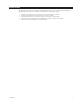
Main Toolbar Cameras Section Video Windows Sherlock Section Date and Time Figure 2. DX9100 Main Window Main Toolbar: The toolbar consists of seven operation buttons. Displays the cameras that are defined in the system by server or by name. Displays the latest events that have occurred in the system by camera or by time. You can define and view new event queries. Unlocks locked video files. You can also view videos that have been locked.
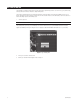
VIEWING LIVE VIDE0 You can view up to four different live videos on a DX9100 viewstation at the same time. 1. Click 2. Click . to expand the server and show all of the cameras. Figure 3. Live Video Cameras Section NOTE: You can right-click a camera to see its properties. to view live video. 3. Click 4. Drag and drop a camera into one of the windows. NOTE: You can also click to select a window. It displays four drop-down buttons.
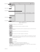
Title Bar Play Bar Figure 4. Video Window Title Bar Moves to the previous video in memory that was displayed in this window. Shows the current camera name and site. Displays a drop-down box of the last 10 videos shown. The most recent video is at the bottom of the list. Moves to the next video in memory that was displayed in this window. Appears on the title bar if the video is live. Switches the video to a larger screen. Play Bar Closes the video window. Rewinds video 1 minute.
VIEWING RECORDED VIDEO You can view up to four different playback (recorded) videos on a DX9100 viewstation at the same time. 1. Click 2. Click . to expand the server and show all of the cameras. Figure 5. Recorded Video Cameras Section NOTE: You can right-click a camera to see its properties. to view playback video. 3. Click 4. Drag and drop a camera into one of the windows. NOTE: You can also click to select a window. It displays four drop-down buttons.
5. 6. Select a date and time. Click Playback. 7. Click while viewing recorded video if you want a bigger view. 8. Click to return to four windows. Title Bar Play Bar Figure 7. Video Window Title Bar Moves to the previous video in memory that was displayed in this window. Shows the current camera name and site. Displays a drop-down box of the last 10 videos shown. The most recent video is at the bottom of the list. Moves to the next video in memory that was displayed in this window.
VIEWING EVENTS Events are videos of specific occurrences that have been marked for your review. There are six types of events that can be identified in the DX9100 viewstation. Each event type is assigned a star with a specific color for easy identification on the time slider. Table A. Event Types Event Type Star Color Description External Input 1 Silver An event imported into the DX9100 system from external devices, such as alarm units or access control systems.
PERFORMING A QUERY 1. Click . 2. Click 3. Select the query parameters. . NOTE: By default, the query includes all events, cameras, and dates and times. Figure 8. Events Section Figure 9.
SELECTED TIME RANGE You can select three different date and time periods: • • • Quick: Perform a quick search within the last x hours or x days. Continuous: Search for events over a specified period. Daily: Search for events every day during the specified dates, between the specified times. For example, search for events every day in the month of January between 20:00 and 22:00. Quick 1. 2. 3. 4. Clear the “No time limits” checkbox. Select the Quick radio button.
SELECTED EVENTS To specify the event types to be included in the query: 1. 2. Clear the “All events” checkbox. Select the events you want to include in the query. Figure 13. Events Query SELECTED CAMERAS To specify the cameras to be included in the query: 1. 2. 3. Clear the “All cameras” checkbox. Click the + next to the server name to view the server’s cameras. Double-click the server name to add all cameras to a query or double-click the camera to add a single camera to a query. 4.
RUNNING THE QUERY 1. Click Preview. The number of events found appears at the bottom of the Preview Window. The events are arranged in descending order by server with the latest event at the top of the list. Up to 2,000 events can be displayed. The star color shows the event type. 2. 3. Click the By Camera tab or By Time tab to view the results by camera or by time. Click OK. The events are transferred to the Events Section and the Query Window closes. Figure 16.
MARKING EVENTS You can mark an event and save it for viewing at a later time. 1. Click while viewing live or playback video. The video picture enlarges. Figure 18. Large Screen Allows you to lock sections of the video and export sections to different media. Shows events. Shows the video on the entire screen. Marks and saves an event. The event is marked in black on the time slider. Increases or decreases the video playback speed. The red button in the center of the speed meter marks the default speed.
SEARCHING FOR MOTION DETECTION The DX9100 Sherlock feature allows you to scan recorded video forward and backward for movement or disappearance of a specific object. 1. Playback the video that you want to scan. 2. Click 3. Click . on the main toolbar is enabled. . The Sherlock section appears. Figure 20. Sherlock Section 4. Select the Event Type. • • Disappearance: The movement is marked as an event only if the marked object disappears completely from its current location.
7. Click in the Sherlock section. The clock at the bottom of the Sherlock section displays the current scanning time and “In progress…” appears. Figure 22. Scan In Progress Message When the scan detects movement of the selected object, it stops and displays the event. A message with the date and time of the event appears. Figure 23. Event Found Dialog Box NOTE: If you marked more than one object, the first scan shows the first object that moved.
LOCKING/UNLOCKING VIDEO Locking the video removes the selected section of video from the first in/first out (FIFO) deletion cycle. You can only lock a section of video and not a current frame. To lock a video: 1. Click while viewing live or playback video. 2. Click . The following window appears. Figure 24. Window for Locking Video 3. Make sure the Video radio button is selected. 4. Select the Start/End date and time. The default is the date and time of the current video.
Figure 25. Dialog Box for Reason to Lock Video 6. Enter a reason for locking the selected video and then click OK. The following message appears. Figure 26. Lock Video Message Only authorized users can unlock a locked video. This video is returned to the FIFO cycle and is deleted according to its location in the queue. To unlock a video: 1. Click . The Lock section appears. Figure 27. Lock Section 2. Select the server from the drop-down box. The locked videos appear in the section. 3.
EXPORTING VIDEO 1. Click 2. Click while viewing live or playback video. . The following window appears. Figure 28. Exporting Video Window 3. Select the Video radio button to save a section of video. 4. Select the Start/End date and time. The default is the date and time of the current video. You can also use the time slider to mark a time period. The selected area is marked in yellow as shown below.
EXPORTING A CURRENT FRAME 1. Click while viewing live or playback video. 2. Click 3. Select the “Current frame” radio button. The following window appears. . Figure 30. Exporting Current Frame Window 4. Export the frame. a. b. c. d. 5. Click File to export the frame and save it in a BMP or JPEG format. Click e-Mail to attach the frame in a JPEG format to an e-mail message. Click Printer to print the frame. Click MS Word to insert the frame into a Word document.
CAMERA RECORDING PROPERTIES Camera recording properties should be set by the system administrator during installation. Only system administrators and operators with a Level 1 authorization can set or change camera recording properties. To set or change camera recording properties, you must open the DX9000 Viewstation application. The System button on the main toolbar is not available to Level 2-6 operators. If you don’t have access, see the system administrator.
2. Click “Select channel” to display a list of recorders. An example is shown below. Figure 32. Select Channel Dialog Box 3. 4. Select a channel. Select the Preview checkbox to verify that you have the correct camera. Figure 33.
CONTINUOUS RECORDING SCHEDULE 1. Select the “Continuous recording” radio button. This is the default setting and should be selected already when you select a channel. Refer to Figure 33. 2. Click Apply. Recording is done at all times and no schedule is defined. The entire daily and weekly recording schedules are marked in light yellow, and any previous definitions on the schedules are removed.
The example below shows a daily Event record schedule from 7:05 a.m. to 12:05 p.m. The box in the time bar is yellow with a red border. You can make the box smaller or larger by dragging it with your mouse. Figure 35. Daily Event Recording Page If you select event recording, the DX9100 actually records continuously. The difference between continuous and event recording is the way the video is saved in the database. When the hard drives are full, the DX9100 starts overwriting the oldest video.
WEEKLY RECORDING SCHEDULE To make sure there is no delay during scheduled recording, begin the recording at least five minutes before the actual recording time. For example, schedule the recording at 7:55 a.m. instead of 8:00 a.m. 1. 2. 3. 4. Select the “Daily recording schedule” radio button. Click Continuous or “Event record.” In the time bar, click the desired start/end times for recording, or enter the exact start/end times in the “Fine tune” fields. Click Apply.
MOTION DETECTION 1. Click the DVMD tab. 2. Select the “Detector on” radio button. 3. Select the Preview checkbox. The video has blue squares over the entire area meaning the entire video has been selected for motion detection. 4. Click “Clear all” to remove all of the boxes, or click the right mouse button on each box you want to remove. 5. Click “Mark all” to select the entire video for motion detection, or click the left mouse button to add individual boxes. 6.
CHANNEL SETUP This section describes how to set camera properties to get the best picture. 1. Click the Video tab. The Video page appears. Refer to Figure 39. 2. Select the Preview checkbox to see the video quality with the default settings. 3. Adjust the video quality by dragging the triangles on the slider bars to the desired values. Refer to Table B. 4. Click Apply. NOTE: The bit rate, located under the “Select channel” button, displays the amount of activity in the specified channel.
Table B. Channel Setup C639M-A (6/04) Parameter Description/Action Channel Name Enter a new name for this channel. You can enter up to 20 characters. Brightness Drag the triangle to change the brightness value. The higher the value, the higher the bit rate. The previous value is displayed to the right of the brightness bar. Contrast Drag the triangle to change the contrast value. The higher the value, the higher the bit rate. The previous value is displayed to the right of the contrast bar.
DEFINING USERS Only system administrators can define user names and passwords for the DX9100 Viewstation. Other users trying to access this option will get the following message: Figure 40. User Access Message Box This option allows an administrator to add, delete, and change the properties of users in the DX9100 system. There are seven predefined user access levels ranging from Administrator to Operator Level 6. Each user is assigned different access rights to the DX9100 network and videos.
Table C. User Access Rights User Administrator Live Video/ Live Events ✓ Video Locked Playback/ Video Query/Sherlock Playback ✓ ✓ Lock Video ✓ Export Image/ Video ✓ Operator Level 1 ✓ ✓ ✓ ✓ ✓ Operator Level 2 ✓ ✓ ✓ ✓ ✓ Operator Level 3 ✓ ✓ ✓ ✓ Operator Level 4 ✓ ✓ ✓ Operator Level 5 ✓ ✓ Operator Level 6 ✓ Unlock Video/ Define Change Camera Users/Audit Settings Viewer ✓ ✓ ✓ Edit Existing Users 1. Select the server name from the “Filter per server” drop-down box.
ADVANCED FEATURES AUDIT VIEWER This is an external software application that is supplied with DX9000 systems. Before using this application, make sure you exit the viewstation application. This application audits every movement by the user in the system regardless of user access rights. All records include category type, time and date of operation, viewstation, and user login ID. For any report generated by the Audit Viewer, there is a maximum of 2,000 records per recorder. 1.
Table D. Audit Viewer Toolbar Icon Description This is the Create New Report icon. Click to modify columns, define filters, and sort columns. This is the Save icon. Click to save the audit report. You can save the report as an HTML, PDF, or TXT file type. This is the Refresh icon. Click to refresh the audit report. This is the Print icon. Click to print the audit report. This is the About icon. Click to display the Audit Viewer version number.
CREATING REPORTS You must define filters before you create a new report. You can define the category, user name, date and time, and computer name. You can also modify columns and sort columns. 1. Go to File > Create Report, or click the Create New Report icon. The following page appears. Figure 44. Modify Columns Page 2. Add or Remove the columns you want to appear on your report. 3. Click the Filter tab. The following page appears. Figure 45.
4. Click the yellow icon next to Categories. The following dialog box appears. Figure 46. Select Category Dialog Box 5. Add or remove categories and then click OK. 6. Click the yellow icon next to Users. The following dialog box appears. Figure 47. Select Users Dialog Box 7. C639M-A (6/04) Add or remove users and then click OK.
8. Click the yellow icon next to Servers. The following dialog box appears. Figure 48. Select Servers Dialog Box 9. Add or remove servers and then click OK. 10. Click the yellow icon next to Date & Time. The following dialog box appears. Figure 49. Select Date & Time Dialog Box 11. Select the date and time range and then click OK. 12. Click the yellow icon next to Viewstations. The following dialog box appears. Figure 50.
13. Add or remove viewstations and then click OK. 14. Click the Order tab. The following page appears. Figure 51. Order Page 15. Change the order of the filter settings. You can move them up or down or in ascending or descending order. 16. Click Create. An example of an audit report is shown in Figure 52. Figure 52. Sample Audit Report NOTE: The Event Time is the local time. The time in the Description column is UTC time.
EXPORT VIEWER The Export Viewer allows you to view exported videos without the DX9000 viewstation. 1. Go to Start > Programs > DX9000 Viewstation > Export Viewer. The following window appears. Figure 53. Export Viewer Window 2. Click Open. The following dialog box appears. Figure 54. Open Video File Dialog Box 3. 42 Select the file you want to view.
4. Click Open. The video plays automatically. Refer to Figure 55. Figure 55. Video Playback The date and time of the video is displayed below the video play bar. The speed control allows you to change the speed at which the video is played. The 0 represents normal speed. Click C639M-A (6/04) to view the video on the entire screen.
VIDEO VERIFIER This is an external software application that is supplied with DX9000 systems. It allows you to verify the authenticity of recorded video by identifying if and where an image or segment of video was changed. You can only browse and verify files that have been exported as MPEG files. NOTE: When you export a video and want to write the data onto a CD, make sure you copy Video Verifier to the same directory as the exported video. 1. Go to Start > Programs > DX9000 Viewstation > Video Verifier.
3. Select the video file and then click Open. Figure 57. Open Verifier File Dialog Box 4. Verification starts automatically. The following preview window shows the first frame of the video being tested. Figure 58.
Table E. Verifier Information Panel Name Description/Action Bit Exact Tests: File structure Checks the syntax of the video file. Integrity watermark Checks that bits in the video file have not been deleted or modified. Authentication watermark Checks the time and date inside the video stream. Video Originality: Ownership DX9000 Server. Video starting date Starting date of the original video. Video starting time Starting time of the original video.
Table F. Failed Test Information Name Description Bit Exact Tests: File structure Indicates that the test has failed. Tested File Info: Name Name of the tested video file. Size Size of the tested video file in bytes. Verification Information: Date Date of the test. Time Time of the test. Version Version of the Video Verifier application. You can do the following from the Video Verifier window. Table G. Video Verifier Buttons Button C639M-A (6/04) Action Start Click to rerun a test.
MAKING A CD OR DVD You can use Nero® to copy data, such as exported video files, onto a CD or DVD. The following steps show how to copy a folder onto a CD. 1. Insert a blank CD into your CD-RW drive. 2. Double-click the Nero StartSmart icon on your desktop. The following window appears. Figure 60. Welcome Window 3. Click CD, and then select the data icon next to the star. Figure 61.
4. Click Make Data Disc. The following window appears Figure 62. Add Files Window 5. Click Add. The following window appears. Figure 63.
6. Select a file or folder, and then click Add. Figure 63 shows a DX9100 folder. Figure 64. Added File Window 7. Click Next. The following window appears. Figure 65.
8. Click Burn. The following dialog box appears when the burn process is completed successfully. Figure 66. Data Verification Dialog Box 9. Click OK. Figure 67.
10. Click Next. The following window appears. Figure 68. Exit Window 11. Click Exit.
SERVER STATE The Server State utility checks the status of the recorders that are connected to the viewstation. It verifies if a recorder is recording, not recording, or unreachable. The Server State application should be running in the background all the time. 1. Go to Start > Programs > DX9000 Viewstation > Server State. Figure 69. Server State 2. Select “All servers” to run the test on all recorders or Server to run the test on a specific recorder. 3. Click Configure.
4. Select the refresh interval. The recommended setting is 60 seconds. Any setting less than 60 seconds will become network intensive because the viewstation constantly polls the recorders. 5. Click OK. 6. Check the “Auto-refresh” checkbox. The application checks the refresh interval when you click start. 7. Check the “Alert on errors or warning” checkbox. The following message appears when an error occurs. Figure 71.
ONLINE STORAGE METER The Online Storage Meter measures how much storage a group of cameras is using in a specific time frame. 1. Go to Start > Programs > DX9000 Viewstation > Online Storage Meter. Figure 72. Online Storage Meter 2. 3. 4. 5. Enter the Server name and the Channel number. Select a specific time frame. Select the graph type. Click Show. Figure 73.
WARRANTY AND RETURN INFORMATION WARRANTY Pelco will repair or replace, without charge, any merchandise proved defective in material or workmanship for a period of one year after the date of shipment. Exceptions to this warranty are as noted below: • Five years on the following fixed camera models: CC3701H-2, CC3701H-2X, CC3751H-2, CC3651H-2X, MC3651H-2, and MC3651H-2X.
® World Headquarters 3500 Pelco Way Clovis, California 93612 USA USA & Canada Tel: 800/289-9100 Fax: 800/289-9150 International Tel: 1-559/292-1981 Fax: 1-559/348-1120 www.pelco.