I N S T A L L A T I O N ID-P Pendant Mount Adapter C2241M (12/09)
Contents Important Safety Instructions. . . . . . . . . . . . . . . . . . . . . . . . . . . . . . . . . . . . . . . . . . . . . . . . . . . . . . . . . . . . . 4 Description . . . . . . . . . . . . . . . . . . . . . . . . . . . . . . . . . . . . . . . . . . . . . . . . . . . . . . . . . . . . . . . . . . . . . . . . . . . 5 Parts List. . . . . . . . . . . . . . . . . . . . . . . . . . . . . . . . . . . . . . . . . . . . . . . . . . . . . . . . . . . . . . . . . . . . . . . . 5 Installation . . . . . . . . .
Important Safety Instructions 1. Read these instructions. 2. Keep these instructions. 3. Heed all warnings. 4. Follow all instructions. 5. Only use attachments/accessories specified by the manufacturer. 6. Installation should be done only by qualified personnel and conform to all local codes. 7. Use only installation methods and materials capable of supporting four times the maximum specified load. 8. Only use replacement parts recommended by Pelco. 9.
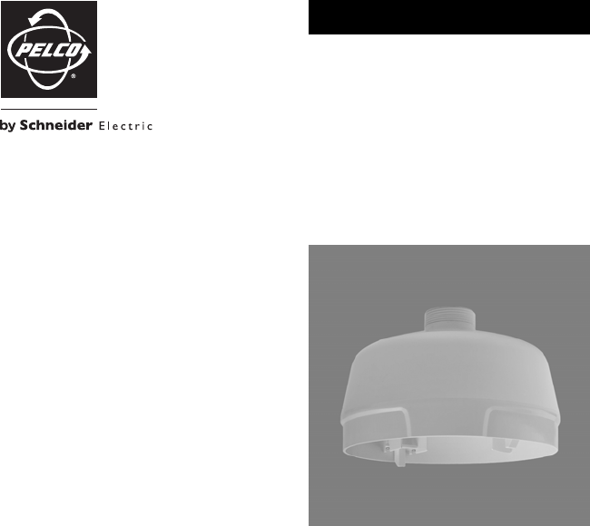
Description The ID-P is a pendant mount adapter specifically designed for ID and IDE Series network dome cameras. The pendant adapter modifies the network dome camera for pendant installations using a 1.5-inch (3.81 cm) NPT mount, such as the SWM-WT mount.
Installation 1. Install the 1.5-inch (3.81 cm) NPT mount; refer to the instructions supplied with the mount. 2. Pull the system power and video wiring through the mount. 3. Route the wiring through the ID-P pendant mount adapter. Apply Loctite (supplied) to the threads of the ID-P, and then screw the pendant mount adapter onto the mount. Figure 1. Installing the Pendant Mount Adapter 4.
5. Connect the network cable to the RJ-45 network port. If the network has no Power over Ethernet (PoE), connect a 24 VAC Class 2 power supply to the 24 VAC power connector. 1 8 Pin 87 8 65 43 21 1 2 3 4 5 6 7 8 1 2 3 4 6 7 8 8 5 1 Function 1 TX+ 2 TX– 3 RX+ 4 PoE 1-2 5 PoE 1-2 7 RX– 7 PoE 3-4 8 PoE 3-4 6 6 5 4 3 2 1 Figure 3. RJ-45 Pin Descriptions 6. Connect the alarm and relay connector: a. Connect the alarm and relay wires to the supplied 4-pin connector. b.
7. If PoE is not available, connect the VAC connector: a. Connect the 24 VAC wires to the supplied 2-pin VAC connector. b. Attach the mating connector to the green connector on the side of the camera. 24V~ Figure 5. 24 VAC Connector NOTE: If you are operating the camera using 24 VAC and you are wiring more than one camera to the same transformer, connect one side of the transformer to the red wire (24 VAC +) and connect the other side of the transformer to the black wire (24 VAC –).
. Apply power to the camera. The camera will complete a configuration sequence: the green LED flashes five times per second for approximately two minutes and then turns solid after the sequence is complete. NOTE: If the camera is not connected to a Dynamic Host Configuration Protocol (DHCP) server and DHCP is enabled, the configuration sequence might take up to five minutes to complete. 10.
Specifications MECHANICAL Mounting Method Attach the ID-P to a mount with 1.5-inch (3.81 cm) NPT pipe (such as the SWM-WT mount) GENERAL Construction Aluminum Finish Polyester powder coat Unit Weight 1.69 lb (0.77 kg) (Design and product specifications subject to change without notice.) 0.54 (1.37) 7.50 (19.05) 5.12 (13.00) NOTE: VALUES IN PARENTHESES ARE CENTIMETERS; ALL OTHERS ARE IN INCHES.
PRODUCT WARRANTY AND RETURN INFORMATION WARRANTY Pelco will repair or replace, without charge, any merchandise proved defective in material or workmanship for a period of one year after the date of shipment.
www.pelco.com Pelco, Inc.