
User's Manual

®
Pelco • 3500 Pelco Way • Clovis, CA 93612-5699 • USA
(800) 289-9100 or (1-559) 292-1981 • FAX (800) 289-9150 or (1-559) 292-3827
International customers call (1-559) 292-1981 or FAX (1-559) 348-1120
PCB1500535ASSY
Board Replacement for RB24,
RB115 and RB24/200 Relay Boxes
Installation Manual
C1915M (6/97)
INSTALLATION INSTRUCTIONS
The PCB1500535ASSY (Rev. D) PC board is part of the RB24, RB115, RB24/220
Relay Boxes. For complete installation and operation instructions, refer to manual
C915M-D.
1. Disconnect power to the relay box.
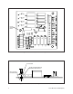
2. Refer to Figure 1. Disconnect the 115 VAC IN plug to the transformer and
disconnect the PAN/TILT OUT, and 24 VAC CONTROL IN connections.
3. Unscrew the three (3) screws attaching the PC board to the relay box and
remove the old PC board. Save the screws and lock washers to attach the
new PC board.
4. Remove the new PC board from the static bag.
5. Refer to Figure 2. Install the top screw first (located near C6). Install the PC
board by putting a lock washer and nylon washer on a screw and inserting it
through the hole in the PC board. Then put a nylon washer under the PC
board and tighten the screw into the standoff as needed. Do not over tighten.
Insert the screws in the bottom holes in the PC board and tighten until firmly
attached.
6. Reconnect the 24 VAC CONTROL IN and PAN/TILT OUT connections, and
the 115 VAC IN plug to the transformer. Reconnect power to the relay box.
CAUTION:
Failure to dis-
connect power will expose
you to a risk of electric
shock.
CAUTION:
It is important,
when screwing down the
PCB1500535ASSY (Rev.
D) PC board to the relay
box, that you use the pro-
vided nylon washers be-
tween the screw, PC board
and top metal standoff.
CAUTION:
Failure to use
nylon washers when attach-
ing the PC board to the top
metal standoff will result in
a short condition damaging
the PC board.