I N S TA L L AT I O N / O P E R AT I O N ® PMC14H and PMC14H-GY 14-Inch Color Monitor C2906M (7/03)
IMPORTANT SAFEGUARDS AND WARNINGS 1. Read these instructions. 2. Keep these instructions. 3. Heed all warnings. 4. Follow all instructions. 5. Do not use this monitor near water. 6. Do not block any ventilation openings. Install in accordance with the manufacturer’s instructions. 7. Do not install near any heat sources such as radiators, heat registers, stoves, or other apparatus (including amplifiers) that produce heat. 8. Do not defeat the safety purpose of the polarized or grounding-type plug.
DESCRIPTION The PMC14H is a high-resolution color monitor that can be used in desktop applications or rack mounted using the optional RMA14F rack mount kit. The monitor supports NTSC and PAL video, as well as 120 VAC and 230 VAC input power. An automatic switching system makes all the necessary changes for adapting to the required formats. Manual selection is not required. A separate power cord is supplied for each voltage input.
INSTALLATION 1. Table A. Video Coaxial Cable Requirements Make all equipment connections as required for your installation. Refer to Figures 1 through 3 for samples of installation methods. Cable Type* RG59/U RG6/U RG11/U Refer to Table A for coaxial cable requirements. 2. Plug power cord into the AC INLET connection on the rear panel of the monitor. Plug the other end into a power receptacle.
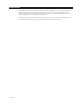
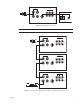
VIDEO V1 AUDIO V2 V1 V2 S-VIDEO IN CAMERA IN OUT OUT S-VIDEO S-VHS OUT AUDIO OUT VCR Figure 2. S-VHS Video Input Connections Note: The S-Video connector is an input connector; there is no loop-through capability using S-Video. VIDEO V1 AUDIO V2 V1 V2 S-VIDEO IN IN CAMERA OUT OUT S-VIDEO VIDEO V1 AUDIO V2 V1 V2 S-VIDEO IN IN OUT OUT S-VIDEO VIDEO V1 AUDIO V2 V1 IN V2 S-VIDEO IN OUT OUT S-VIDEO VCR Figure 3.
OPERATION 1. Press the POWER button to turn the monitor on. The LED above the power button will illuminate when the monitor is on. 2. Select the camera by pressing the V1, V2, or S-VIDEO button (refer to Figure 4). 3. If required adjust the picture using the control knobs on the front panel. Refer to Figure 4 for front panel controls. FRONT PANEL ADJUSTMENTS TINT Color phase adjustment. Turn clockwise to increase the greenish tones in the picture.
SPECIFICATIONS ELECTRICAL Input Voltage: Power Consumption: Horizontal Resolution: Visual Picture Size: Sweep Linearity: Speaker Output: 100-240 VAC, 50/60 Hz, automatic switching 45 watts 450 TV lines, center of screen 14-inch (35.56 cm) diagonal 10% 1.0 watt (-3 dBV) GENERAL Input/Output Video: Audio: S-Video: Construction: Finish PMC14H: PMC14H-GY Dimensions: Weight: 2 BNC inputs, 75 ohms or Hi-Z 2 looping outputs 3 RCA inputs, Hi-Z 3 looping outputs 1 DIN input Steel cabinet Black Gray 13.
WARRANTY AND RETURN INFORMATION WARRANTY Pelco will repair or replace, without charge, any merchandise proved defective in material or workmanship for a period of one year after the date of shipment. Exceptions to this warranty are as noted below: • Five years on Pelco manufactured cameras (CC3500/CC3600/CC3700 and MC3500/ MC3600 Series); two years on all other cameras. • Three years on Genex® Series (multiplexers, server, and keyboard) and 090 Series Camclosure® Camera System.