® DD5TA Series Dome Drive Installation/ Operation Manual C1498M-B (7/99) UL ® LISTED Pelco • 300 W. Pontiac Way, Clovis • CA 93612-5699 USA • Pelco Online @ http://www.pelco.
CONTENTS Section Page IMPORTANT SAFEGUARDS AND WARNINGS ................................................................ 3 DESCRIPTION ................................................................................................................... 3 MODELS .................................................................................................................... 3 INSTALLATION ...................................................................................................................
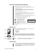
IMPORTANT SAFEGUARDS AND WARNINGS Observe the following warnings before installing and using this product. 1. Installation and servicing should only be done by qualified service personnel and conform to all local codes. 2. Unless the unit is specifically marked as a NEMA Type 3, 3R, 3S, 4, 4X, 6, or 6P enclosure, it is designed for indoor use only and it must not be installed where exposed to rain and moisture. 3. Only use replacement parts Pelco recommends. 4.
CAUTION: Make sure the dome drive locks into place. Pull down on the dome drive with moderate pressure to ensure that it stays in place. 2. Set the switches on the bottom of the dome drive. Refer to Table A for the settings for SW1, and Table B and Table C for SW2. 3. Install the dome drive in the back box. Line up the green tab and red tab on the dome drive with the green label and red label on the back box.
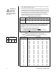
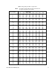
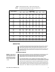
Table C. Switch Settings for SW2 – D-Type Control NOTE: For Coaxitron® controls, SW2 is not used; set all switches OFF. For P-type control systems, refer to Table B.
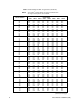
Table C. Switch Settings for SW2 – D-Type Control (Continued) NOTE: For Coaxitron® controls, SW2 is not used; set all switches OFF. For P-type control systems, refer to Table B.
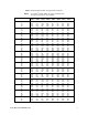
Table C. Switch Settings for SW2 – D-Type Control (Continued) NOTE: For Coaxitron® controls, SW2 is not used; set all switches OFF. For P-type control systems, refer to Table B.
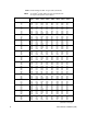
Table C. Switch Settings for SW2 – D-Type Control (Continued) NOTE: For Coaxitron® controls, SW2 is not used; set all switches OFF. For P-type control systems, refer to Table B.
Table C. Switch Settings for SW2 – D-Type Control (Continued) NOTE: For Coaxitron® controls, SW2 is not used; set all switches OFF. For P-type control systems, refer to Table B.
PAN AND TILT FUNCTIONS Use your controller’s joystick to control pan and tilt operation. • Fixed-Speed Controllers – Pan and tilt operation is at a fixed speed; the controller determines the speed. • Variable-Speed Controllers – Depending on the joystick’s position, standard pan operation ranges from 0.5 to 80 degrees per second (dps); standard tilt operation ranges from 0.5 to 40 dps. When performing preset operations, pan speed is 250 dps; tilt speed is 200 dps.
Software controls scan limit stops. When the dome reaches one, it immediately reverses direction. Refer to the Limit Stops section to program the scan limit stops. Program preset 96 (29) to stop a scan. Any pan and tilt or lens command also stops a scan. PARK If the dome does not receive any commands for a specified period, it goes to preset 1 and parks. The dome will not park if the time specified is zero or preset 1 has not been programmed. The default is zero minutes.
CM9750 1. Turn the KEY SWITCH to the ON position. 2. Press the PROG key. PROGRAM appears on the LCD screen. 3. Press the PRES key. The PRESET prompt appears. 4. Enter 95 and press the ENTER key. The main menu appears. 5. Turn the KEY SWITCH to the OFF position. CM9760 1. In the default menu, select DEF. The Define Submenu appears. 2. Enter your four-digit PIN. 3. Enter 95 and select PRST. The main menu appears on the monitor. 4. Select the Quit icon to return to the default menu.
GAIN/AGC AGC Mode The two AGC (Automatic Gain Control) modes are auto and off. • In auto mode, the dome automatically adjusts the gain–the amount of amplification the camera places on its video information to obtain a full 1-volt peak-to-peak video signal out. If the iris is manually opened to its wide-open position and the picture is weak, the AGC can be turned off and the gain increased manually to improve the picture.
6. Move the joystick up or down to position the cursor beside one of the choices. Press the Iris Open button. MODE – The cursor moves to one of two choices: Auto or Off. In the Auto mode, the iris is automatically adjusted to produce a constant video output as determined by the Level setting below. In the Off mode, auto iris is disabled, and control is always manual. Move the joystick up or down to toggle between Auto and Off.
To change the mode: 1. 2. 3. 4. 5. 6. 7. 8. On the main menu, move the joystick up or down to position the cursor (>) beside Camera. Press the Iris Open button to enter the Camera submenu. Move the joystick up or down to position the cursor beside Next. Press the Iris Open button to go to the next camera submenu. Move the joystick up or down to position the cursor beside Auto-Focus Mode. Press the Iris Open button. The cursor moves to the right beside the word Auto or Off.
To change the line synchronization settings: 1. On the main menu, move the joystick up or down to position the cursor (>) beside Line Sync. 2. Press the Iris Open button. Another menu appears with the Line Sync and Line Sync Phase selections. 3. Move the joystick up or down to position the cursor beside one of the choices. LINE SYNC – Move the joystick up or down to toggle between On and Off. Press the Iris Open button to select the choice.
LIMIT STOPS The two types of limit stop are manual and scan. When manual limit stops are set, a manual (joystick) pan operation stops when a limit is reached. When scan limit stops are set, the dome reverses direction during random, frame, and auto scanning when a limit stop is reached. Software controls limit stops. To set limit stops: 1. 2. Turn on limit stop mode. Program the limit stops. Turning Limit Stops On or Off To change the limit stop mode: 1. 2. 3. 4. 5. 6.
3. Move the joystick up or down to position the cursor beside Scan Speed deg/s. 4. Press the Iris Open button. The cursor moves to the right beside the current number of degrees. 5. Move the joystick up or down to toggle through the number of degrees (1-40) until you reach the number you want. (If set on a low number, the scan will appear to barely move but is still functioning.) 6. SELECT – Press the Iris Open button to select your choice.
8. If the red power LED is lit, turn off power. a. Open the door to the interconnect circuit board and check that all connectors are fully seated. b. Make sure the wiring is correct between the unit and controller. c. Close the door. Check the switch settings on the dome drive (refer to Tables A, B, and C) and reinstall the dome drive. d. Turn on power. If the unit still does not operate, turn off power and replace the dome drive with a unit that is good, if you have a spare.
Sensitivity: Signal Process: Sync System: White Balance: Shutter Speed: 1 lux at f1.6 at signal level of 40 IRE, gain high (AGC on) DSP-3R AC line lock Automatic with manual override* Automatic (electronic iris)/manual NTSC 1/60 – 1/10,000* PAL 1/50 – 1/10,000* Iris Control: Automatic with manual override* Gain Control: Automatic with manual override* Video Output: .714 V ±.