® 00961 DX7000 Series Digital Video Recorder Installation/ Operation Manual C682M-E (11/01) Pelco • 3500 Pelco Way • Clovis, CA 93612-5699 USA • www.pelco.
CONTENTS IMPORTANT SAFEGUARDS AND WARNINGS ...................................................... 5 DESCRIPTION ................................................................................................................ 6 MODELS .................................................................................................................... 6 INSTALLATION ..............................................................................................................
INSTALLING THE DX7000CD (CD-RW Drive) ...................................................... 38 LOADING THE DIRECTCD SOFTWARE ................................................................. 41 HOW TO OPERATE THE CD-RW ............................................................................ 41 INITIATE DX7000 COPY BUTTON ................................................................... 41 PREPARING CD-RW MEDIA FOR BACKUP ...........................................................
(This page intentionally left blank.
IMPORTANT SAFEGUARDS AND WARNINGS Prior to installation and use of this product, the following WARNINGS should be observed. 1. Installation and servicing should only be done by qualified service personnel and conform to all local codes. 2. Unless the unit is specifically marked as a NEMA Type 3, 3R, 3S, 4, 4X ,6 or 6P enclosure, it is designed for indoor use only and it must not be installed where exposed to rain and moisture. 3.
DESCRIPTION The DX7000 Series are high-quality digital video recorders (DVR) that combine the functions of a recorder and multiplexer into a product with versatile recording and playback functions. The units are capable of dual operation and can record and play back video at the same time. All models have an input signal of 120/230 VAC and are NTSC/PAL compatible.
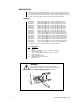
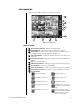
INSTALLATION Place the DVR on any flat surface (desk or table) or install in any standard 19-inch (48.26 cm) wide console or rack configuration. 00589 Figure 1. Rear View of Back Panel NOTE: Set the PAL/NTSC Switch to the proper setting for your application. Refer to 7 . NOTE: An UPS (Uninterrupted Power Supply) is not supplied with the DVR.
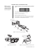
TWO-WIRE CONTROL SYSTEM INSTALLATION NOTE: The PTZ must be set to accept ‘D’ protocol control. For information on setting the receiver address for D-type control, refer to the documentation supplied with the PTZ equipment. 1. Connect the control wires from the receiver to the RS-422 converter. The DX7000 can support up to 16 PTZ devices. To connect more than one PTZ to the system, refer to Figure 3. RS-422 Converter Receiver TX+ RX+ TX- RX- 2.
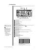
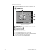
PROGRAMMING Turn the system power ON; the Main Screen (DISPLAY mode) appears. 00582 Figure 5. Display Mode DISPLAY MODE 1 Date and Time Indicator – Displays current date and time. 2 SEARCH Button – Plays back and search recordings by date and time. 3 SETUP Button – Programs camera settings, customize a recording schedule, set up multiple password levels, and establish pan and tilt protocol. 4 PTZ Control Button – Controls pan, tilt, and zoom functions. Sets patterns, tours, and presets.
DX7000 SYSTEM SETUP To setup the DX7000 Digital Video Recorder use the left mouse button and click on the SETUP button located in the DISPLAY mode. CAMERA SETUP 1 2 3 4 01177 Figure 6. Channel Setup Menu 1 CAMERA NAME Box 2 SIGNAL TYPE – Selection must correspond with the NTSC/PAL selection switch setting. Refer to Figure 1, item 7 . 3 CAMERA ENABLE Button 4 CAMERA SELECTION Button Use the following steps to set up a camera site. 10 1.
COLOR SETUP 1 2 3 4 5 7 6 00959 Figure 7. Color Setup Menu 1 CON – Adjusts the CONTRAST of the viewed and recorded scene. 2 BRI – Adjusts the BRIGHTNESS of the viewed and recorded scene. 3 RED – Adjusts the RED level of the viewed and recorded scene. 4 GREEN – Adjusts the GREEN level of the viewed and recorded scene. 5 BLUE – Adjusts the BLUE level of the viewed and recorded scene. 6 DEFAULT COLOR – Return all level settings to their defaults.
SCHEDULE SETUP 1 2 3 9 4 5 6 8 7 01201 Figure 8. Schedule Setup Menu 12 1 GROUP (01-24) – Selects group to be scheduled. 2 Sets START TIME and END TIME for recording group. 3 Schedule Selection Buttons CLEAR ALL SCHEDULE – Clears all GROUP (1-24) schedules. FULL RECORD – Adds all cameras and days to GROUP 1. SENSOR TO CAMERA – Automatically selects the camera sensor for a GROUP in a one-to-one ratio (Camera 1, Sensor 1, Group 1).
Evaluate the flow of motion at the surveillance site before programming a schedule. A recording schedule can consist of one of the following modes and/or a combination of all modes: NORMAL – Continuous recording recommended for surveillance areas with a lot of movement. MOTION – Saves disk space; records only when motion is detected. SENSOR – Saves disk space; records only when an alarm is activated.
SPEED SETUP 1 11 2 3 4 10 5 6 9 8 7 01203 Figure 9. Speed Setup Menu 1 RECORDING SPEED MODE a. NORMAL – Sets recording speed for continuous recording. b. MOTION – Sets motion detection and pre-alarm recording speeds. c. SENSOR – Sets sensor detection and pre-alarm recording speeds. 2 IMAGE QUALITY – Sets the compression size of the recorded image. 3 MOTION EXT. DURATION – Records time after motion is detected. 4 SENSOR EXT. DURATION – Records time after a sensor is triggered.
MOTION DETECTION SETUP 1 2 3 4 01192 Figure 10. Motion Detection Setup Menu Pelco Manual C682M-E (11/01) 1 BEEP – Beeps when motion is detected. 2 SENSITIVITY – Adjusts the sensitivity of the detection areas. 3 CLEAR ALL BLOCK – Deletes all motion detection area blocks. 4 Motion Detection Area – To select a detection area move the pointer to the desired area. Hold down the left mouse button and drag over the area. Release the left mouse button to end selection.
PASSWORD SETUP 1 2 3 4 5 01195 Figure 11. Password Setup Menu 1 SELECT LEVEL – Levels include Administrator, Search User, PTZ/Backup User, and Client User. 2 INPUT AREA – Password input window. 3 NUMBER BUTTONS – Use number buttons to input password. 4 ENTER – Select to apply password to level. 5 CLEAR – Clears password input area. To set a password: 1. 2. 3. Select the level. Press the number buttons to input a password. Click the ENTER button to apply the password input.
PAN & TILT SETUP 1 01197 Figure 12. Pan and Tilt Protocol Menu 1 Select pan and tilt protocol by scrolling through the selections in the RX TYPE box. QUIT TO EXPLORER The DX7000 uses a Window’s based operating system. To set a network address, add hardware, or change clock settings click the Quit To Explorer button. When exiting Windows Explorer the message “System will be shutdown” appears. Select cancel to return to the DX7000 system DISPLAY mode. Do not press OK.
OPERATION RECORDING STATUS The colored circle located to the right of the on-screen camera title indicates the recording status of the camera. RED indicates that the camera is recording continuously. If the circle is BLUE, camera recording was triggered by motion detection. YELLOW indicates sensor input recording, and a CLEAR circle means the camera is not currently recording.
PATTERN A pattern is a user-defined, viewable camera path with a definite beginning and end. The pattern can consist of any standard pan and tilt or lens commands. Once defined the pattern is easily activated with the press of an on-screen menu button. The pattern will run continuously until it is deactivated with another press of the menu button. How to Program a Pattern 1. Click the PTZ button in the DISPLAY Mode. The PTZ Mode appears. 2. Select a camera. 3.
PRESET TOURS A preset tour is a programmed sequential execution of preset positions. How to Program a Preset Tour 1. Click the PTZ button in the DISPLAY Mode. The PTZ Mode appears. 2. Click the left mouse button on PRESET. 3. Select a camera by moving the cursor to the desired camera view and clicking the left mouse button. 4. Click the TOUR button to turn it ON. 3. Click the SET button to turn it ON. 5. Click preset buttons in any sequential order to program a tour. 6.
SEARCH CONTROL MODE 1 2 3 4 5 6 15 14 10 8 13 12 11 9 7 01202 Figure 15. Search Control Menu 1 Date and Time Indicator – Displays current date and time. 2 Search Date – Displays year, month, and time of search. 3 Search Window – Flashes when system is searching through cameras. 4 Search Index Button – Shows or hides search index. 5 Exit – Exits to display mode. 6 Playback Buttons – Refer to Figure 16. 7 Backup Button – Search button for backup storage device.
SELECT DATE AND TIME 1. Enter the year and month in the SEARCH DATE area of the menu. Click the up or down arrow buttons to make a selection. 2. Enter the hour and minute in the SEARCH DATE area of the menu. Click the arrow buttons up or down to make a selection. 3. Click the CALENDAR BUTTON. 4. The calendar menu appears in the lower left-hand corner of the screen. 5. Dates with recordings are highlighted with a yellow circle. Click a highlighted date. 6.
BACKUP TO 3.5-INCH DISKETTE 1. Press the CAMERA SELECTION button. 2. Disable all cameras in search mode. FDD backup cannot be done when the viewing screen is divided. 3 Select one camera. 4. Click the FDD button. The BACKUP window appears. 5. Select how many images will be saved. The total number of copies is limited to 30 images at one time. 6. Select file type (BMP or JPG). 7. Click on OK. PRINT IMAGE 1. Press the CAMERA SELECTION button. 2. Disable all cameras in search mode.
REMOTE SITE SOFTWARE DESCRIPTION Free remote site software is included with the DX7000 to provide remote site viewing of live and recorded video. The software is compatible with Windows 98 and Windows 2000. INSTALLATION To install the remote users software: 1. 2. 3. 4. 5. Start Windows 98 or Windows 2000. Close all programs, including any anti-virus programs. Insert the Remote Users Software CD into the CD-ROM drive. The Windows 98 Setup wizard starts. Follow the instructions that appear.
REGISTERED SITE SETUP 1 3 5 7 10 9 2 4 6 8 Figure 18. Setup Screen 1 Date and Time Indicator – Displays current date and time. 2 SITE NAME – Enters the name of the site. 3 ADDRESS – Inputs the IP address or phone number of site. 4 5 PASSWORD – Use only if the DX7000 registered site is CLIENT USER password protected. The password must be the same as the registered site password for CLIENT USER. SWITCH SPEED (Sequencing speed) – Set the sequencing time between cameras.
OPERATION 1 2 3 4 9 8 7 6 5 01178 Figure 19. Online Mode 1 Date and Time Indicator – Displays current date and time. 2 SEARCH Button – Plays back and searches recordings by date and time. 3 PTZ Control Button – Controls pan, tilt, and zoom functions. 4 CONNECT/DISCONNECT Button – Connects to the domain site or disconnects from the domain site. AVI Button – Creates and saves an AVI file to a backup storage device. To view saved AVI files use a PC Media Player that supports the AVI file format.
9 Screen Division – Single camera display Displays cameras 1-9 Quad display, cameras 1-4 Displays cameras 10-16 Quad display, cameras 5-8 Displays all 16 cameras Quad display, cameras 9-12 Sequencing mode – Sequence using single, four, or nine camera displays. Quad display, cameras 13-16 Full-screen display – Removes menu bars from display. Click the right mouse button to return to previous screen display. To connect to a remote site: 1. 2. 3.
VIEW It is not necessary to use the screen division buttons located in the lower left corner of the screen to change the camera view. You can use the left and right mouse buttons to instantly view a single camera or remove the menu bars from the display. To change screen view: 1. Move the cursor to the desired camera view and click with the left mouse button. A single view of the selected camera appears. 2.
PATTERN A pattern is a user-defined, viewable camera path with a definite beginning and end. The pattern can consist of any standard pan and tilt or lens commands. Once defined the pattern is easily activated with the press of an on-screen menu button. The pattern will run continuously until it is deactivated with another press of the menu button. How to Program a Pattern 1. Click the PTZ button in the DISPLAY Mode. The PTZ Mode appears. 2. Select a camera. 3.
PRESET TOURS A preset tour is a programmed sequential execution of preset positions. How to Run A Preset Tour 1. 2. 3. 4. Click the PTZ button in the DISPLAY Mode. The PTZ Mode appears. Click the left mouse button on PRESET. Click the TOUR button, the preset tour starts. To stop the tour click the TOUR button. PATTERN BAR PRESET BAR FOR FUTURE USE PRESET BUTTONS CAMERA 01196 Figure 21.
SEARCH MODE 1 2 3 4 5 6 7 9 8 00955 Figure 22. Search Mode Pelco Manual C682M-E (11/01) 1 Date and Time Indicator – Displays current date and time. 2 Search Date – Selects month and year to search video. 3 Search Time – Selects the time (hour and minute) to search video. 4 Select Camera – Reviews video of selected camera. 5 Copy and Print Buttons – Saves a recorded image to a diskette, prints an image or creates and saves an AVI file to a backup storage device.
SELECT DATE AND TIME 1. Enter the year and month in the SEARCH DATE area of the menu. Click the up or down arrow buttons to make a selection. 2. Enter the hour and minute in the SEARCH DATE area of the menu. Click the arrow buttons up or down to make a selection. 3. Click the CALENDAR BUTTON. 4. The calendar menu appears in the lower left-hand corner of the screen. 5. Dates with recordings are highlighted with a yellow circle. Click a highlighted date. 6.
EMERGENCY AGENT SOFTWARE 00950 Figure 24. Emergency Agent Window Emergency Agent software alerts the remote site client of any triggered alarm at the surveillance site. When an alarm is triggered a popup widow appears on the monitor of the remote site client. The window displays a detailed list (date and time) of all images recorded during the alarmed event. To view the transmitted images use the playback buttons located at the bottom of the Emergency Agent software window.
BACKUP VIEWER SOFTWARE Use the Backup Viewer software to search images stored on backup media, DAT tape or DVD disc. To install the Backup Viewer: 34 1. Start Windows 98. 2. Close all programs, including any anti-virus programs. 3. Insert the Remote Users Software CD into the CD-ROM drive. 4. The Windows 98 Setup wizard starts. Follow the instructions that appear. 5. The DX7000 Series software installation program appears. Click on the Backup Viewer software button and follow the instructions.
BACKUP VIEWER OPERATION 1 2 3 4 5 6 15 14 10 8 13 12 11 9 7 01202 Figure 25. Backup Viewer Pelco Manual C682M-E (11/01) 1 Date and Time Indicator – Displays current date and time. 2 Search Date – Displays year, month, and time of search. 3 Search Window – Flashes when system is searching through cameras. 4 Search Index Button – Shows or hides search index. 5 Exit – Exits to display mode. 6 Playback Buttons – Refer to Figure 16.
WATERMARK TOOL The Watermark tool allows you to verify if an original image has been altered. The Watermarking Viewer software is available on the Remote Site Software CD. To install the Watermark Viewer: 1. Start Windows 98. 2. Close all programs, including any anti-virus programs. 3. Insert the Remote Users Software CD into the CD-ROM drive. 4. The Windows 98 Setup wizard starts. Follow the instructions that appear. 5. The DX7000 Series software installation program appears.
RED FRAME SHADING MESSAGE Figure 27. The Image Has Been Altered 00957 There are three indications that an image has been altered: Pelco Manual C682M-E (11/01) 1. A red frame around the image. 2. The image is shaded. 3. The message “Image has been altered or has not been watermarked” appears in the lower left-hand corner of the screen.
INSTALLING THE DX7000CD (CD-RW DRIVE) 1. Connect one end of the USB data cable to the CD-RW drive. Connect the other end of the USB data cable to the USB serial port (1 or 2) located on the back panel of the DX7000 DVR. Do not connect the power supply to the CD-RW drive at this time. Refer to Figure 28. BACK OF CD-RW USB DATA CABLE BACK OF DX7000 DO NOT CONNECT POWER TO THE CD-RW DRIVE UNTIL THE DRIVER SOFTWARE DISK HAS BEEN INSTALLED IN THE A:\ DRIVE OF THE DX7000 SYSTEM.
6. Click Next. The following message appears: 01182 7. Select Search for the Best Driver for Your Device.
8. Select Floppy Disk Drives and click Next. The following appears: 01184 9. Accept the recommended driver by clicking Next. The following window appears: 01185 10. Click Finish. 11. After installing the driver remove the floppy disk from the A:/ drive. Exit Explorer, and then select OK to shutdown the system. 12. Restart the DX7000 system by pushing the ON/OFF switch located on the front panel.
LOADING THE DirectCD SOFTWARE 1. From the DISPLAY mode of the DX7000 click on the SETUP button. The SETUP mode appears. 2. Click the EXIT TO EXPLORER button. Windows Explorer appears. 3. Insert the hp cd-writer installation software – disc 1 into the CD-RW drive. 4. Select the CD-RW drive and click Setup. The Start Installation window appears. 01200 5. Click Start Installation and follow the instructions that appear on the screen.
PREPARING CD-RW MEDIA FOR BACKUP NOTE: The initial format of a CD-RW disk can take a considerable amount of time, approximately three hours. To speed up the procedure of copying files to a backup device, always have a formatted CD-RW disc readily available. The Initial Formatting of CD-RW Media Using the DX7000 DVR The following procedure is recommended for the initial format of a CD-RW disk. 1. Insert the CD-RW disc in the CD-RW drive. 2. From the DISPLAY mode of the DX7000 click the SETUP button.
8. Select the CD-RW drive and click Next. The following appears: 01209 9. Type the title of the CD-RW in the place provided, and then select Finish. The following dialog box appears. 01210 10. Select OK; fast format is initiated. Approximately three minutes will pass and the following dialog box appears: 01206 The dialog box indicates that fast format has been initiated.
BACKUP WINDOW 1 2 3 4 12 5 11 6 10 9 8 7 01180 Figure 29. Backup (COPY) Window 1 SELECT DRIVE box – Lists drives with files available for backup. 2 STORED ITEMS box – Lists all files stored in the selected drive. 3 ADD button – Adds stored files to ITEMS TO BACKUP box. 4 ITEMS TO BACKUP box – Lists files selected for backup 5 CLEAR ALL button – Clears all files in the ITEMS TO BACKUP box. 6 SPACE NEEDED indicator – Shows the amount of space required to backup selected files.
HOW TO BACKUP (COPY) TO THE CD-RW DRIVE 1. From the DISPLAY mode of the DX7000, click the COPY button. The SETUP mode appears. NOTE: If the COPY button is not available it has not been initiated. Refer to the Initiate DX7000 Copy Button section of this manual. 2. Click the COPY button. The backup window appears. 3. Select a drive from the SELECT DRIVE box. After several minutes a list of files will appear in the STORED ITEM(S) box. 4. Use the left mouse button and select file/files to backup.
DX7000EM (External Modem) CONNECT THE EXTERNAL MODEM TO THE DX7000 1. Connect the 25-pin end of the RS-232 cable (supplied with the modem) to the serial port located on the back panel of the modem. 2. Connect other end of the RS-232 cable to the COM 2 serial port located on the back panel of the DX7000. 3. Connect one end of the supplied telephone cable to the modem port labeled JACK. 4. Connect the other end of the cable to the telephone wall jack. 5.
LOAD THE DRIVER FOR THE MODEM 1. From the DISPLAY mode of the DX7000, click the EXIT button. A dialog box appears. Select Yes. The DX7000 shuts off. 2. Turn ON the modem and restart the DX7000 system by pushing the ON/OFF switch located on the front panel. 3. The DX7000 detects the new hardware. After a few seconds the Add New Hardware Wizard pops-up on the screen with the following message: 01187 4.
5. Select Search for the Best Driver for Your Device. Click Next, the following appears: 01189 6. Type C:\Windows\System in the space provided. Click Next, the following appears: 01190 7. Accept the recommended driver by clicking Next.
8. Click Finish, the DX7000’s DISPLAY mode appears. 9. From the DISPLAY mode of the DX7000 click the SETUP button. The SETUP mode appears. 10. Click the SPEED button. The SPEED SETUP window appears. a. Check the Use Modem box. b. Check the Duplex box. 11. Exit SETUP to return to the DISPLAY mode.
SPECIFICATIONS ELECTRICAL/VIDEO Input Voltage: 100-240 VAC switchable, 50/60 Hz Signal System: NTSC/PAL CPU & RAM DX7008: DX7016: Celeron, 128 MB Pentium® III, 128 MB Resolution NTSC: PAL: 320 x 240 384 x 288 Compression: M-JPEG Compressed Image Size: 52 x 240; average 6KB Video Inputs: 8 or 16, depending on model Video Outputs: 2 (1 SVGA, 1 analog) Alarm Inputs: 8 Control Outputs: 8 Remote Control: Full remote control via PSTN, ISDN, TCP/IP Pan/Tilt/Zoom Control: RS-422 interface to
NOTES Pelco Manual C682M-E (11/01) 51
PRODUCT WARRANTY AND RETURN INFORMATION WARRANTY Pelco will repair or replace, without charge, any merchandise proved defective in material or workmanship for a period of one year after the date of shipment. Exceptions to this warranty are as noted below: • Five years on FT/FR8000 Series fiber optic products. • Three years on Genex ® Series products (multiplexers, server, and keyboard).