ADDENDUM Addendum No.: Date: Manuals Affected: Manual Update: C1577M-A August 4, 2004 CM9760 Series Manuals – C538M-A, C539M-A, C540M-B, C541M-C, C542M-B, C543M-A, C544M, C549M-A, C572M, C573M-D, C578M, C579M, C1501M, C1503M, C1510M-QS, C1510M-A, C1520M-B, C1528M-D, C1940M, C1941M, C1942M, and C1943M The CM9760-CC1 has been replaced with the CM9700-CC1 and the CM9760-MGR management software has been replaced with the CM9700-MGR management software.
® CM9760-VCRC VCR Controller Installation/ Operation Manual C1941M (7/98) Pelco • 3500 Pelco Way • Clovis, CA 93612-5699 USA • www.pelco.
CONTENTS Section Page 1.0 GENERAL .................................................................................................. 5 1.1 IMPORTANT SAFEGUARDS AND WARNINGS ............................... 5 1.2 REGULATORY NOTICES .................................................................. 5 2.0 DESCRIPTION .......................................................................................... 6 2.1 MODELS ...........................................................................................
LIST OF ILLUSTRATIONS Figure 1 2 3 4 5 6 7 8 9 10 11 12 13 14 15 16 17 18 Page Front View of CM9760-VCRC ............................................................ 7 Front Panel Removal .......................................................................... 7 DIP Switch Location ........................................................................... 8 Rear View of CM9760-VCRC ............................................................. 9 VCR Input Plugs ...........................................
(This page intentionally left blank.
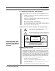
1.0 GENERAL 1.1 IMPORTANT SAFEGUARDS AND WARNINGS Prior to installation and use of this product, the following WARNINGS should be observed. 1. Installation and servicing should only be done by qualified service personnel and conform to all local codes. 2. Unless the unit is specifically marked as a NEMA Type 3, 3R, 3S, 4, 4X ,6 or 6P enclosure, it is designed for Indoor use only and it must not be installed where exposed to rain and moisture. 3. Only use replacement parts recommended by Pelco. 4.
2.0 DESCRIPTION The CM9760-VCRC is another optional accessory of the System 9760™. This VCRC gives security and surveillance operators the ability to automatically or manually control appropriate VCRs from the 9760 matrix system. It is designed to remotely control seven basic VCR functions using two different control methods; resistive ladder remote control and S-Link remote control. Currently, it supports Sanyo and Sony model resistive ladder VCRs and Sony model S-Link VCRs.
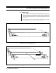
3.0 PRE-INSTALLATION INFORMATION 3.1 FRONT VIEW Figure 1 illustrates the front view of the unit. Power and data LEDs occupy opposite ends of the front panel. The power LED on the left is green and the data LED on the right is red. All other connectors, switches, inputs and outputs are on the rear of the unit except for two DIP switches and a reset switch located behind the front panel cover plate.
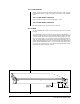
3.1.1 DIP Switches With the front panel removed, DIP switch 1 and DIP switch 2 are visible. These two ten-position DIP switches configure and define many functions of the CM9760VCRC. 3.1.1.1 DIP Switch Locations Figure 3 identifies the relative locations of DIP switches 1 and 2. 3.1.1.2 DIP Switch Functions DIP switch functions are discussed in Section 3.3, SETUP. 3.1.2 LEDs The green POWER LED located on the left front panel of the unit comes ON at power up.
3.2 REAR VIEW The rear of the unit is illustrated in Figure 4. From left to right are the following: NOTE: VCR block ranges are assigned specific VCR type via slide switches 7 through 10 on DIP switch 2. 1. The four 16-input blocks of VCR connectors in the form of screw-type connectors with associated mating plugs (one shown in Block 1) running from the left rear to middle right of the unit 2. The VCRC output relay (one per unit) 3. RS-422 input/output communication connectors (RJ-45 type) 4.
3.2.1 Input VCR Connectors Physically, each of the four VCRC input connectors consists of the same number of input screw-type terminals. Each input group uses a dual-row removable plug and each plug is associated with 8 VCR inputs. IMPORTANT: Control cable length should not be extended further than the supplied 20 feet because resistive ladder input circuits are very susceptible to additional line impedance.
3.2.2 Relay Output Connector Figure 6 illustrates the relay output connector and its relative port pin assignments. The connector is a three-position plug with screw-type contacts similar in operation to the mating connectors just discussed. By default, the relay is in its normal state at power up of the unit as shown in Figure 6.
3.2.3.1 DB-9 Connector Pin-outs The DB-9 connector is reserved for factory use only. 3.2.3.2 RJ-45 Connector The RJ-45 connector pin-outs are illustrated in Figure 7. Because both RJ-45 connectors have the same wiring pin-outs, they require the same “flipped” cable. In other words, the IN connector requires a “flipped” cable for connecting the first unit to the CC1, and the OUT connector requires a “flipped” for cascading other units.
3.2.4 Power Connections The CM9760-VCRC utilizes an auto-ranging internal transformer circuit that allows the input power to range from 100-240 VAC @ 50/60 Hz. Associated with the input power is the power ON/OFF switch and the input power fuse. The fuse is easily changed as illustrated in Figure 9. IMPORTANT: IT IS IMPORTANT TO ACTIVELY AVOID INTRODUCING CURRENT GROUND LOOPS IN YOUR CONFIGURATIONS WHEN HOOKING UP A VCRC AND ITS ASSOCIATED VCRs TO POWER SOURCES.
3.3 SETUP 3.3.1 Preliminary Discussion NOTE: It is highly recommended that VCRC address # 1 (Frame Address 0) be used first, VCRC address # 2 second, and so on, to minimize programming confusion. NOTE: GPIs are programmed using the 9760 System Manager program. See Section 3.3.3, Software Setup–Using the MGR Program to Configure VCRC Operation, for introductory instructions. For detailed programming instructions, refer to the Systems Manager manual.
NOTES: ANY OF THE 11 VCRCS MAY BE ASSIGNED ANY OF THE USEABLE EVEN FRAME ADDRESSES IN ANY ORDER YOU WISH (KEEP IN MIND THE SPECIFIC RECOMMENDATION MADE IN THE NOTES ON THE PREVIOUS PAGE). JUST REMEMBER THAT THE FRAME ADDRESS USED IS ASSOCIATED WITH A SPECIFIC VCR RANGE. IF YOU TRY TO CONTROL A VCR THAT DOESN'T FALL WITHIN THE VCR RANGE, NOTHING WILL HAPPEN. Figure 10.
3.3.3 Software Setup–Using the MGR Program to Configure VCRC Operation The VCRC unit controls up to 64 VCRs per unit and provides seven basic functions of VCR control direct from the CM9760 keyboard. These controls include Stop, Pause, Play, Eject Fast Forward, Rewind and Record. The VCRC accepts GPI commands issued under call functions of VCR control via direct key entry or through properly prepared Macros. Access to GPI functionality is setup in the MGR program in the following manner.
NOTE: When writing macros to control VCR operation, keep in mind the following: The macro must reflect your actual equipment configuration; if you change the configuration, you must adjust the macro accordingly. For example, if a macro were written to control VCRs attached to three VCRCs in a daisy-chained configuration and one of the VCRCs was subsequently removed, then any previously written macro that included these three VCRCs would have to be rewritten to reflect that change.
10. Define operator access, save the GPI file, return to the MGR main menu screen and press the tab to bring up the COMMS file (.SCP file). Refer to Figure 13. 11. In the COMMs file assign an equipment number “17” to the port on the CC1 that will be used for communicating to the VCRC. Also, set communication settings for 9600 baud and even parity.
4.0 INSTALLATION Physical installation of the VCRC unit is relatively simple, although various configurations are possible. 4.1 DIRECT RACK-MOUNT HOOK-UP Regardless of the location of a VCRC unit, it will more than likely be installed in a rack (refer to Figure 14). The VCRC unit mounts in a standard 19-inch (48.26 cm) rack and occupies only one RU (1.75" or 4.45 cm) of rack space. 4.
4.3 DAISY-CHAINING Up to eleven VCRCs may be daisy-chained together. This enables the system to support up to 700 VCRs. Figure 15 illustrates the required wiring connections for daisy-chaining. Note that the remarks made in the previous section regarding RS-422 wiring run distances also applies here when considering cables distance runs between daisychained units.
5.0 OPERATIONAL OVERVIEW The basic function of the VCRC unit is to act as an interface between the user/ operator of the system and any connected VCRs. Each VCRC processes and executes only commands with addresses that match the controller address. When a VCRC receives a command with an inappropriate address it passes it on to the next unit (if applicable) via its OUT port. When power is first applied to the unit, RAM is cleared and initialization routines are called.
5.2 OPERATING THE CM9760-VCRC FROM THE CM9760-KBD Direct control operation of VCRs attached to VCRCs from a CM9760-KBD is relatively straightforward. Once the system is running and the keyboard is on-line, direct control of a VCR is as follows: 1. Select an input (camera) that was programmed as a VCR on the keyboard. This will cause the keyboard’s LCD to change to the VCR control menu illustrated in Figure 18. 2.
6.0 SPECIFICATIONS Electrical Input Voltage: Auto-ranging 100-240 VAC, 50/60 Hz Power: Consumption: 30 vA Data Ports Input: RS-422, RJ-45 connector DIP switch selectable baud rate Output: RS-422, RJ-45 connector. DIP switch selectable baud rate Output: DB-9 connector Factory use only Indicators: 2 power LEDs, green 1 activity LED, red Fusing: 500 mA, 250 V Relay Out: Load rating for relay contacts: 0.50 A at 125 VAC or 1 A at 24 VDC General Dimensions 19.37" W x 1.73" H x 8.15" D (49.
7.0 WARRANTY AND RETURN INFORMATION WARRANTY Pelco will repair or replace, without charge, any merchandise proved defective in material or workmanship for a period of one year after the date of shipment. Exceptions to this warranty are as noted below: • Five years on FT/FR8000 Series fiber optic products. • Three years on Genex® Series products (multiplexers, server, and keyboard).