
User's Manual


Pelco Manual C1941M (7/98) 3
REVISION HISTORY
Manual # Date Comments
C1941M 7/98 Original version.
LIST OF ILLUSTRATIONS
Figure Page
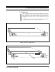
1 Front View of CM9760-VCRC ............................................................7
2 Front Panel Removal..........................................................................7
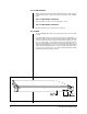
3 DIP Switch Location ...........................................................................8
4 Rear View of CM9760-VCRC.............................................................9
5 VCR Input Plugs ...............................................................................10
6 Relay Output Connector ................................................................... 11
7 RJ-45 Pin-outs ..................................................................................12
8 RJ-45 Connector Pin-out Geometry .................................................12
9 Power Input Fuse Replacement ........................................................13
10 DIP Switch Functions ........................................................................15
11 Configuring MGR Camera File for VCRC Operation.........................16
12 Configuring the GPI SETUP file for VCRC Operation ....................... 17
13 Configuring the COMMS file for VCRC Operation ............................ 18
14 CM9760-VCRC Rack-Mount Installation ..........................................19
15 Daisy-Chain Configuration ................................................................ 20
16 Daisy-Chain Multi-Buss Configuration ..............................................20
17 VCRC Functional Block Diagram ......................................................21
18 CM9760-KBD VCR Control Functions ..............................................22