Q U I C K S T A R T G U I D E PMVC4/PMVR2 Multiviewer Multiple Image Display System C2929M (5/06)
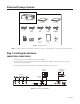
Illustrated Package Contents - OR PARTS BOX PMVC4 MULTIVIEWER DVI CABLE 10” (25.4 cm) DB9 CABLE (LOOPING) SCREWS (8) 6’ (1.8 m) DB9 CABLE (TO PC) RACK MOUNT EARS PMVR2 MULTIVIEWER USA STANDARD POWER CORD (110 VAC) EUROPEAN STANDARD POWER CORD (220VAC) QUICK START GUIDE INSTALLATION CD RS-232 TO RS-485 CONVERTER Figure 1. Package Contents NOTE: For detailed information on the installation, configuration, and operation of the multiviewers, consult the manual on the installation CD.
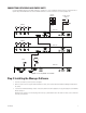
CONNECTING MULTIPLE PMVC4 UNITS Remember, when cascading PMVC4s, loop from the multiviewer with a lower ID to the multiviewer with a higher ID. Also, the following additional steps are required when connecting multiple units. 1. Use a flat head screwdriver on the rotary Unit ID switch to set the ID of the first multiviewer in the display group to 0. This identifies it in the software as the first multiviewer.
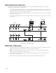
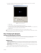
DISPLAY MONITOR PC AND CONTROL MONITOR VMX300 DX8000 VGA OR DVI OUTPUT VGA 1 DVI 1 DVI 2 VGA 2 ON OFF COM IN 01 2 EF 89 67 A 345 BCD Cascade In VGA Out Cascade/DVI Out Unit ID COM OUT 100-240 VAC PMVR2 Figure 4. Connecting a Single PMVR2 CONNECTING MULTIPLE PMVR2 UNITS Remember, when cascading PMVR2s, loop from the multiviewer with a lower ID to the multiviewer with a higher ID. Also, the following additional steps are required when connecting multiple units. 1.
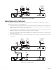
CONNECTING BOTH PMVC4 AND PMVR2 UNITS In cascading PMVC4 multiviewers with PMVR2 multiviewers, remember to loop from a multiviewer with the lower ID to a multiviewer with a higher ID. Begin with PMVC4 multiviewers and then PMVR2 multiviewers. Follow the instructions for connecting multiple units.
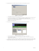
4. The program displays the Set Total Monitor dialog box, which determines how many display groups you have. Figure 7. Set Total Monitor Dialog Box • • • • Set the number of monitors (up to 50 monitors). You must set this first. If you click the Auto Set check box, the program will quickly set up a single group or multiple groups. (If you do not click the Auto Set check box, the program will bypass steps 6 and 7. Skip the following instructions and go directly to Step 8.
. The program next displays the Set Monitor Type dialog box. The settings in this dialog box are optional. They are only a graphic representation of the system and do not actually affect the system itself. Figure 9. Set Monitor Type Dialog Box • • • • Select the group. Use the zoom buttons to decrease or increase the image on the control screen. Select values for ratio and size. Click the Apply All check box to apply the ratio settings to all the images.
PRODUCT WARRANTY AND RETURN INFORMATION WARRANTY Pelco will repair or replace, without charge, any merchandise proved defective in material or workmanship for a period of one year after the date of shipment. Exceptions to this warranty are as noted below: • Five years on FR/FT/FS Series fiber optic products and TW3000 Series unshielded twisted pair transmission products. • Three years on Genex ® Series products (multiplexers, server, and keyboard).