
User's Manual


2 C2929M (5/06)
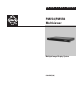
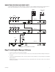
Illustrated Package Contents
Figure 1.
Package Contents
NOTE:
For detailed information on the installation, configuration, and operation of the multiviewers, consult the manual on the installation CD.
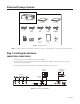
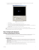
Step 1: Installing the Hardware
CONNECTING A SINGLE PMVC4
1. Connect the cameras to the video BNC inputs on the back of the PMVC4.
2. Connect the male end of the 6-foot (1.8-meter) DB9 serial cable to COM IN on the PMVC4. Connect the other end (with the RS-232-to-
RS-485 converter) to the PC’s COM port.
3. Connect either a DVI cable from Cascade/DVI Out or a VGA cable from VGA Out to the display monitor.
Figure 2.
Connecting a Single PMVC4
INSTALLATION CD
PMVC4 MULTIVIEWER
PARTS BOX
PMVR2 MULTIVIEWER
- OR -
USA STANDARD
POWER CORD
(110 VAC)
EUROPEAN
STANDARD POWER
CORD (220VAC)
RS-232 TO RS-485
CONVERTER
QUICK START
GUIDE
DVI CABLE
6’ (1.8 m)
DB9 CABLE
(TO PC)
10” (25.4 cm)
DB9 CABLE
(LOOPING)
SCREWS (8) RACK MOUNT EARS
PMVC4
0
1
2
3
4
6
7
8
9
A
B
C
D
E
F
5
100-240 VAC
VGA Out
Cascade In
Unit ID
COM IN
COM OUT
Video 1 Video 2 Video 3 Video 4
Cascade/DVI Out
DISPLAY
MONITOR
VGA OR DVI
OUTPUT
CAMERAS
PC AND CONTROL
MONITOR