
User's Manual


4 C2929M (5/06)
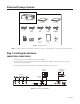
Figure 4.
Connecting a Single PMVR2
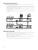
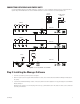
CONNECTING MULTIPLE PMVR2 UNITS
Remember, when cascading PMVR2s, loop from the multiviewer with a lower ID to the multiviewer with a higher ID. Also, the following
additional steps are required when connecting multiple units.
1. Use a flat head screwdriver on the rotary Unit ID switch to set the ID of the first multiviewer in the display group to 0. This identifies it in the
software as the first multiviewer. Change the ID of every additional multiviewer in the group by increments of one; for example, the next
multiviewer will have an ID of 1. Do not use F, which is for testing only.
2. Connect any DVI inputs (such as from a VMX300 video management system) to the DVI 1 and 2 connectors or any VGA inputs (such as from
a DX8000 series digital video recorder) to the VGA 1 and 2 connectors on the back of the PMVR2.
3. Connect a 10-inch (25.4-centimeter) DB9 serial cable from COM OUT on unit 0 to COM IN on the next unit, which is unit 1. Repeat until you
reach the last unit in the group.
4. Connect a DVI looping cable from Cascade/In on unit 0 to Cascade/DVI Out on the next unit, which is unit 1. Repeat until you reach the last
unit in the group.
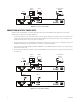
Figure 5.
Connecting Multiple PMVR2s
0
1
2
3
4
6
7
8
9
A
B
C
D
E
F
5
DVI 1
VGA 1
DVI 2
VGA 2
VGA Out
ON OFF
100-240 VAC
COM IN
COM OUT
Cascade In
Unit ID
Cascade/DVI Out
PMVR2
DX8000
PC AND CONTROL
MONITOR
DISPLAY
MONITOR
VMX300
VGA
OR DVI
OUTPUT
0
1
2
3
4
6
7
8
9
A
B
C
D
E
F
5
DVI 1
VGA 1
DVI 2
VGA 2
VGA Out 100-240 VAC
COM IN
COM OUT
Cascade In
Unit ID
Cascade/DVI Out
PMVR2 ID0
DISPLAY
MONITOR
DX8000
VMX300
PC AND CONTROL
MONITOR
VGA
OR DVI
OUTPUT
0
1
2
3
4
6
7
8
9
A
B
C
D
E
F
5
DVI 1
VGA 1
DVI 2
VGA 2
VGA Out 100-240 VAC
COM IN
COM OUT
Cascade In
Unit ID
Cascade/DVI Out
PMVR2 ID1
DX8000
DX8000