QUICK START GUIDE PMCD750 DLP™ Display 50-Inch Rear Projection Display C2928M-QS (7/05)
This quick start guide describes basic assembly and operation of the PMCD750 DLP™ display as a stand-alone unit and as part of a video wall.
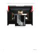
Chassis Assembly WARNING: The chassis weighs 65 lb (29.5 kg). Two people are required to handle and position the display safely. Unpack the PMCD750 unit. The screen is not needed yet and should be left in its container at this time. SINGLE DISPLAY Attach the screen support to the front edge of the chassis with the supplied screen support bolts. The screen support mounts only one way. It incorporates a stop (rest) for the screen. Refer to Figure 1.
WALL DISPLAY – SECOND ROW AND UP DANGER: Because the PMCD750 unit has a narrow front-to-back profile, the danger of tipping exists with high walls. For walls over two units high and all tilted walls, use the four tie-back points (1/4-20 threaded holes) on the rear of the unit to secure the video wall to a structural part of the building. If the wall is tilted forward, tie the wall all the way up. Do this as the wall is being built up; do not wait until the wall is finished.
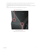
WARNING: The maximum stack height for a wall is four units. 1. Stack another row of PMCD750 units on the first row. As you stack, be careful inserting the alignment pins on the second row chassis into the alignment holes on the lower unit. Refer to Figure 3. SECOND ROW ALIGNMENT PIN DETAIL ALIGNMENT PINS ALIGNMENT HOLES FIRST ROW Figure 3.
2. As each unit is placed in the second row, secure it to the front of the lower unit with two 6-32 x 3/8-inch screws. Refer to Figure 4. FRONT SCREW CONNECTION POINTS FRONT SCREW CONNECTION POINT DETAIL Figure 4.
3. Bolt the PMCD750 units together vertically through the vertical connection points using the 1/4-20 x 3/8-inch bolts. Refer to Figure 5. 4. Bolt the PMCD750 units together through the bottom connection points the same as the first row. Refer to Figure 1. 5. Bolt the PMCD750 units together through the horizontal connection points using the 1/4-20 x 2-inch bolts, washers, and wing nuts. Refer to Figure 5. 6. Continue in this way with the rest of the rows, checking straightness as each row is completed.
Connecting Analog and Digital Sources The PMCD750 will accept video input from devices with VGA or DVI output. Video sources with either or both of these output types can have their images displayed on the PMCD750. Refer to Figure 6. IN OUT IN OUT LOOPING VGA LOOPING DVI LOOPING VIDEO SOURCE OUTPUT FIRST DISPLAY SECOND DISPLAY Figure 6. Video Input Connections Connect the video input to the Analog 1, Analog 2, or Digital In input. Multiple inputs can be connected simultaneously.
Connecting RS-232 and RS-485 Control Serial control can be used with stand-alone units, a wall, or several walls. To connect an external controller: 1. Using a straight-through computer serial cable, connect the RS-232 input of the stand-alone unit or the first unit in the wall to the serial out port of the external control device, such as a video controller. Refer to Figure 7. 2. Connect this first display’s RS-485 Out to the next display’s RS-485 In. Refer to Figure 7.
Installing Screens To install a screen on a stand-alone unit, follow the instructions in steps 1a, 1b, and 1c. 1. To install the PMCD750 screens, start in the middle of the bottom row and install that screen. The screen supports should be installed on the bottom row of PMCD750 screens. a. Pull the screen rails all the way out on both sides of the PMCD750 chassis. The screen rails each have a large pin that mates with the L-shaped slot located on each side of the screen. Refer to Figure 8. b.
Figure 9.
Connecting Power 1. Bring AC power next to the electronics module. Connect the power to the receptacle located on the rear panel. The voltage can be 115 VAC (90–132 VAC) or 230 VAC (200–254 VAC). Refer to Figure 10. POWER SWITCH AC OUT AC IN Figure 10. Power Switch and Receptacles WARNING: Do not exceed the recommended number of PMCD750 units linked in series for AC power or the current draw will be too great. 2.
Using The Remote Control Using the the remote control is the only way to access menu settings. There are no access controls on the display unit. The remote control projects a series of IR (infrared) pulses to the PMCD750 display for control. Aim the remote control at a single display and press MENU. The main menu should be visible if the lamp is on. Refer to Figure 11 for remote control buttons and their associated commands/ actions.
Alignment and Adjustment If the image on the screen is not positioned accurately, alignment of the optical engine may be required. It is important to check this mechanical adjustment of the optical engine before any electronic adjustments are made to the picture. Refer to the Aligning the Optical Engine section of the Installation/Operation manual. If the aspect ratio of the image does not match that of the display, scaling and cropping adjustments can be made to compensate.
PRODUCT WARRANTY AND RETURN INFORMATION WARRANTY Pelco will repair or replace, without charge, any merchandise proved defective in material or workmanship for a period of one year after the date of shipment. Exceptions to this warranty are as noted below: • Five years on FT/FR8000 Series fiber optic products. • Three years on Genex ® Series products (multiplexers, server, and keyboard).
Worldwide Headquarters 3500 Pelco Way Clovis, California 93612 USA USA & Canada Tel: 800/289-9100 Fax: 800/289-9150 International Tel: 1-559/292-1981 Fax: 1-559/348-1120 www.pelco.